Concrete structure connecting joint with sliding support

A technology of concrete structures and sliding bearings, which is applied to building structures, bridge materials, buildings, etc., can solve the problems of waste of materials, construction methods, and complexity, and achieve the effects of simple construction, improved connection strength, and convenient installation

Pending Publication Date: 2021-08-13
CHINA CONSTR EIGHT ENG DIV CORP LTD
View PDF0 Cites 0 Cited by
  • Summary
  • Abstract
  • Description
  • Claims
  • Application Information

AI Technical Summary

Problems solved by technology

[0004] Aiming at the deficiencies in the prior art, the present invention provides a concrete structure connection node with a sliding support to solve the problem of material waste or complicated construction methods in the prior art in which steel bar bending anchors are integrally formed. The problem

Method used


Image

  • Concrete structure connecting joint with sliding support
  • Concrete structure connecting joint with sliding support
  • Concrete structure connecting joint with sliding support

Examples


Embodiment 1

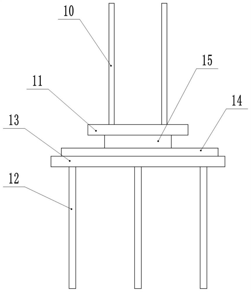
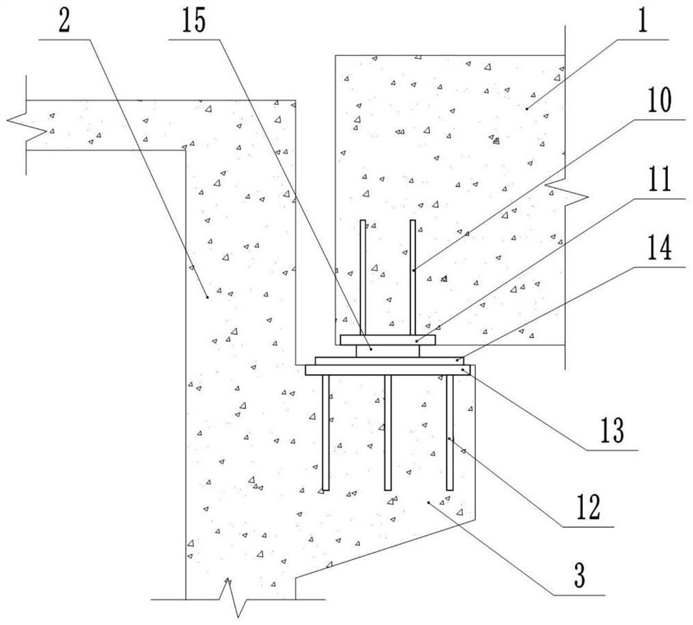
[0032] basically as figure 1 and figure 2 As shown, a concrete structure connection node with a sliding bearing is arranged between the concrete member I1 and the concrete member II2. The concrete member I1 is located above the concrete member II2. When it needs to be connected with the side wall of the concrete member II2, then The corbel 3 is poured on the side wall of the concrete member II2, so that the corbel 3 is located below the concrete member I1, and a first embedded part is embedded at the bottom of the concrete member I1, and the first embedded part includes a first leg 10 and a first embedded part. The steel plate 11 and the first legs 10 are provided with a number of them and are vertically evenly distributed on the first steel plate 11. The first legs 10 and the first steel plate 11 are buried in the concrete member I1, and the bottom surface of the first steel plate 11 is exposed to the concrete member. I1.

[0033] The top of the concrete member II2 is embe...

Embodiment 2

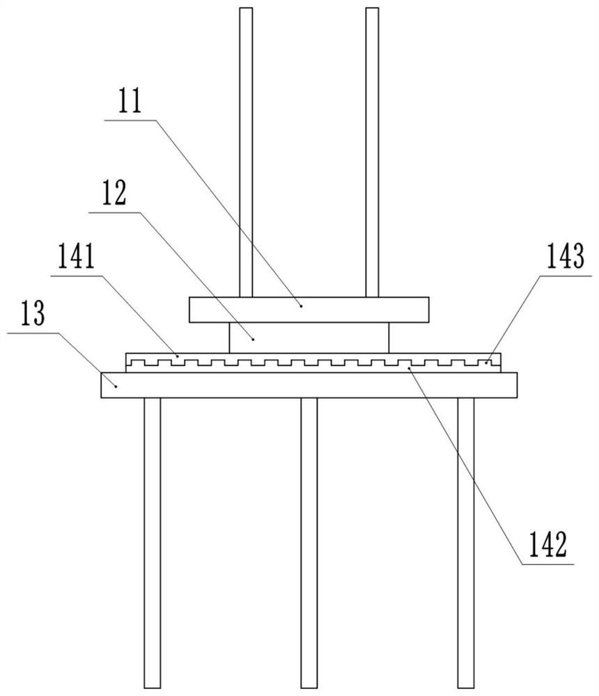
[0037] The difference from Example 1 is that: the combination image 3 As shown, the adjusting steel plate 14 includes a limit steel plate 141 and a top-tightening steel plate 142. A number of horizontally arranged clamping grooves are opened at the bottom of the limiting steel plate 141, and the clamping grooves are distributed at equal intervals. The top of the top-tightening steel plate 142 is integrally formed with A number of clips 143 corresponding to the card slots; when installing, first glue the bottom of the rubber support 15 to the top of the limit steel plate 141, then coat the top of the rubber support 15 with adhesive, and then put it into the gap Inside, move the limit steel plate 141 upward to bond the top of the rubber support 15 to the bottom of the first steel plate 11. At this time, the distance between the bottom of the limit steel plate 141 and the top of the second steel plate 13 is D1, and the thickness of the pressing steel plate 142 is D2, where D1<D2...

Embodiment 3

[0039] The difference from Example 2 is that: the combination Figure 4As shown, both the top and the bottom of the rubber support 15 are in an arc shape concave to the inside of the rubber support 15 . This arrangement reduces the overflow of the adhesive during the extrusion bonding process, thereby improving the connection strength between the rubber support 15 and the adjustment steel plate 14 and the first steel plate 11; in addition, if the top and bottom of the rubber support 15 are flat, Then, in the process of inserting the top-tightening steel plate 142 to drive the rubber bearing 15 to deform, the deformation of the rubber bearing 15 will be concentrated in the middle of the rubber bearing 15, so that the stress will be concentrated and the fatigue resistance of the rubber bearing 15 will decrease. Therefore, this solution is adopted. , in the process of inserting the top-tightening steel plate 142 to drive the rubber support 15 to deform, since the top and bottom o...


PUM


Abstract

The invention belongs to the technical field of building construction and particularly discloses a concrete structure connecting joint with a sliding support. The concrete structure connecting joint with a sliding support is arranged between a concrete member I and a concrete member II, the concrete member I is positioned above the concrete member II, a first embedded part is embedded in a bottom part of the concrete member I, a second embedded part right opposite to the first embedded part is embedded in a top part of the concrete member II, and a rubber support is arranged between the first embedded part and the second embedded part. By using the scheme, the first embedded part, the second embedded part and the rubber support form a combination of brand new connecting members from top to bottom. A problem of connection between the independent concrete members is solved and adverse effects caused by relative displacement between the members are relieved. An adverse effect caused by size errors generated in a pouring forming process of the concrete members is relieved.

Description

technical field [0001] The invention belongs to the technical field of building construction, and particularly relates to a concrete structure connecting node with a sliding bearing. Background technique [0002] The connection structure between two or more relatively independent concrete structures needs to be considered in multiple directions, 1) the shear force and braking force generated by the relative displacement between the independent concrete members need to be considered; 2) the concrete members under load The shock absorption and buffering requirements caused by the horizontal displacement between the two parts and the deflection at the end; 3) The dimensional error that generally exists in the process of pouring and forming of concrete members, and the error is amplified at the connection of structural members, resulting in adverse effects, and Concrete components themselves are affected by environmental factors, such as creep and other factors. [0003] At pre...

Claims


Application Information

Patent Timeline
IPC IPC(8): E04B1/38E04B1/36E04B1/41E01D19/00E01D19/02E01D19/04E01D101/24E01D101/30
CPCE01D19/00E01D19/02E01D19/041E01D2101/24E01D2101/30E04B1/36E04B1/38E04B1/41
Inventor 孔瀚玉何兴陈丁谭建国纪俊宏艾敬淞刘原卢爱民文川文胜钦
Owner CHINA CONSTR EIGHT ENG DIV CORP LTD
Why Eureka
Try Eureka