Injection valve fault diagnosis method, system and equipment and storage medium

A fault diagnosis and injection valve technology, applied in mechanical equipment, fuel injection control, engine control, etc., can solve the problems of air pressure value influence, misdiagnosis, etc., reduce workload and labor intensity, achieve accurate diagnosis results, and realize precise diagnosis Effect

Active Publication Date: 2021-08-13
WEICHAI POWER CO LTD +1
View PDF8 Cites 2 Cited by
  • Summary
  • Abstract
  • Description
  • Claims
  • Application Information

AI Technical Summary

Problems solved by technology

[0004] However, because each component of the fuel pipeline has an impact on the air pressure value, there is a risk of misdiagnosis in fault diagnosis based solely on pressure changes

Method used


Image

  • Injection valve fault diagnosis method, system and equipment and storage medium
  • Injection valve fault diagnosis method, system and equipment and storage medium
  • Injection valve fault diagnosis method, system and equipment and storage medium

Examples


Embodiment Construction

[0046] The following will clearly and completely describe the technical solutions in the embodiments of the present invention with reference to the accompanying drawings in the embodiments of the present invention. Obviously, the described embodiments are only some, not all, embodiments of the present invention. Based on the embodiments of the present invention, all other embodiments obtained by persons of ordinary skill in the art without making creative efforts belong to the protection scope of the present invention.

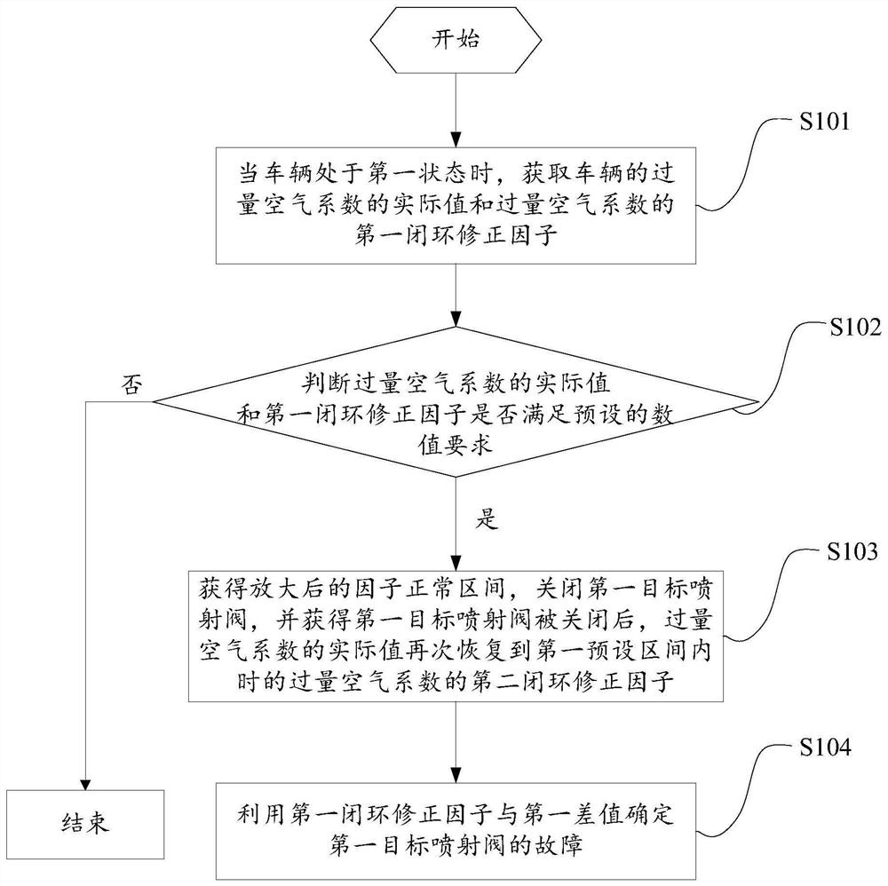
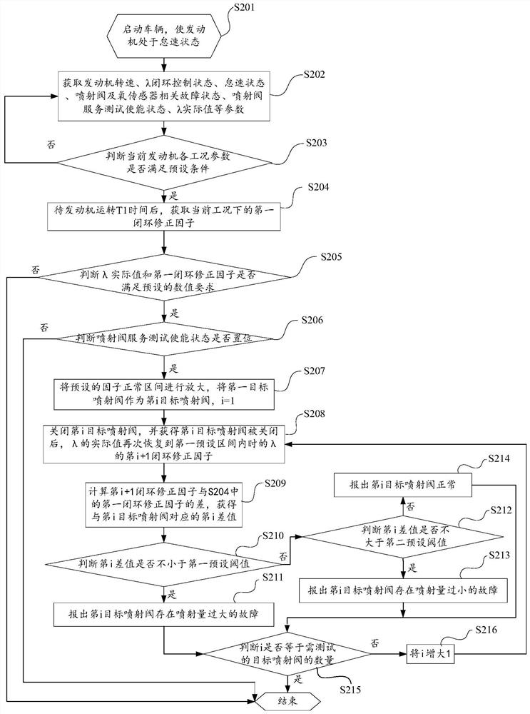
[0047] An embodiment of the present invention provides a method for diagnosing an injection valve fault, such as figure 1 As shown, the above methods include:

[0048] S101. When the vehicle is in the first state, acquire an actual value of the excess air ratio of the vehicle and a first closed-loop correction factor of the excess air ratio.

[0049] Wherein, the first state may include: at least one condition in which the engine speed is within a preset rang...


PUM


Abstract

An embodiment of the invention provides injection valve fault diagnosis method, system and equipment and a storage medium. The method comprises the steps that when a vehicle is in a first state, an actual value of an excess air coefficient of the vehicle and a first closed-loop correction factor are obtained, whether the actual value is within a first preset interval and whether the first closed-loop correction factor is within a preset factor normal interval are judged, and if the actual value is within the first preset interval and the first closed-loop correction factor is within the preset factor normal interval, after the amplified factor normal interval is obtained, a first target injection valve is closed, a second closed-loop correction factor of the excess air coefficient after the actual value is recovered to the first preset interval after the first target injection valve is closed is obtained, a first difference value between the second closed-loop correction factor corresponding to the first target injection valve and the first closed-loop correction factor is obtained, and the fault of the first target injection valve is determined through the first closed-loop correction factor and the first difference value. Accurate diagnosis of the fault of the injection valve of an engine can be achieved under the condition that the engine is not disassembled, and the general applicability is high.

Description

technical field [0001] The invention relates to the field of engine detection, in particular to an injection valve fault diagnosis method, system, equipment and storage medium. Background technique [0002] During the use of the engine injection valve, there is a deviation between the actual fuel flow and the required flow due to wear, sticking, foreign matter blockage, etc., which affects engine performance and even causes safety accidents. [0003] At present, for the fault diagnosis of the injection valve, the first rail pressure of the fuel rail before the injection valve is opened and the second rail pressure after the engine has been running for a period of time are usually collected, and the difference between the first rail pressure and the second rail pressure is obtained. The rail pressure drop value is compared with the preset drop threshold value to judge whether there is a fault in the injection valve. [0004] However, because each component of the fuel pipeli...

Claims


Application Information

Patent Timeline
Patent Type & Authority Applications(China)
IPC IPC(8): F02D41/22F02D41/14
CPCF02D41/22F02D41/14F02D2041/224Y02T10/40
Inventor 曹石魏倩雯黄美丽王梦
Owner WEICHAI POWER CO LTD
Why Eureka
Try Eureka