Rifle bore locking device for preventing misoperation and special wrench

A locking device and misoperation technology, applied in the direction of safety devices, offensive equipment, weapon accessories, etc., can solve the problems of potential safety hazards, lack of rifles to prevent reloading and firing, reloading and shooting misoperations, etc., to prevent false firing , Improve the safety of use, and the effect of reliable work

Active Publication Date: 2021-08-13
青岛哈船海厚机电技术有限责任公司
View PDF5 Cites 0 Cited by
  • Summary
  • Abstract
  • Description
  • Claims
  • Application Information

AI Technical Summary

Problems solved by technology

[0002] Due to the lack of locking devices to prevent reloading and firing of existing rifles, it is easy for training and on-duty personnel to reload and shoot after obtaining rifles and ammunition Misoperation, causing greater safety hazards

Method used


Image

  • Rifle bore locking device for preventing misoperation and special wrench
  • Rifle bore locking device for preventing misoperation and special wrench
  • Rifle bore locking device for preventing misoperation and special wrench

Examples


Embodiment 1

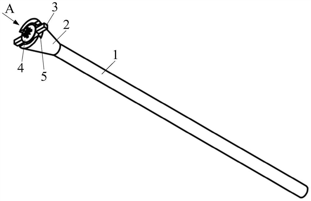
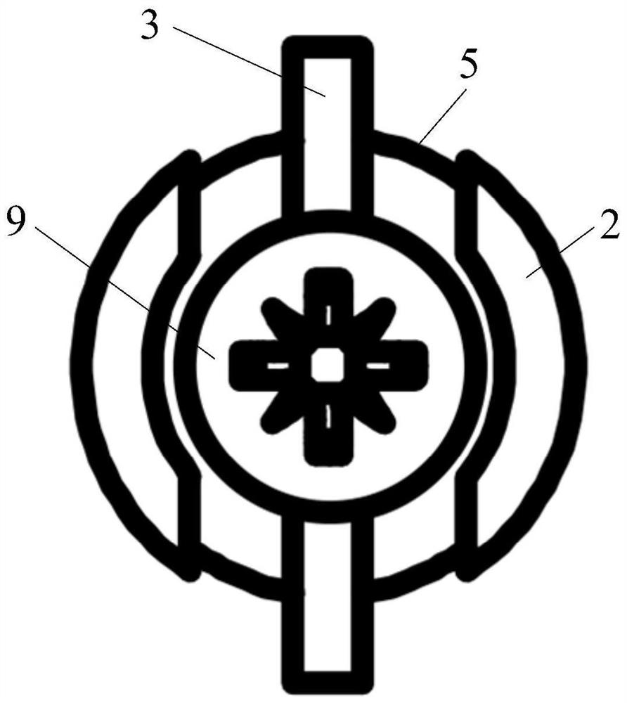
[0032] Such as figure 1 with figure 2 As shown in the structure, the chamber locking device includes a breech rod 1, a conical pressure plate 2, a locking pin 3 and a screw 4; Conical structure, and has a large-diameter end and a small-diameter end; the small-diameter end of the conical pressure plate 2 is fixedly connected to one end of the chamber rod 1, and the large-diameter end is threaded with the screw 4; the locking pin 3 is compressed by the screw 4 On the conical platen 2.

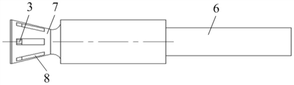
[0033] The above-mentioned rifle chamber locking device is used in the gun barrel 6 of the rifle to prevent misoperation, during specific use, such as image 3 As shown in the structure, the breech rod 1 extends from the end of the gun barrel 6 into the gun bore to block the gun bore, the conical pressure plate 2 matches the shape of the inner cavity of the flame arrester 7 at the end of the gun barrel 6, and passes through the conical pressure plate 2 and the flame arrester 7 are positioned,...

Embodiment 2

[0043] Additionally, if Figure 4 As shown in the structure, the embodiment of the present invention also provides a special wrench 11 used in conjunction with any one of the breech locking devices in the first embodiment above. . Special wrench 11 is used for the installation and dismounting of anti-theft screw 4, and the screw head 9 of anti-theft screw 4 is provided with the special-shaped groove 10 of irregular shape, can prevent adopting common wrench to carry out disassembly to anti-theft screw 4, realizes to the gun bore lock Control the disassembly and assembly of the stop device to prevent disassembly and installation by anyone without permission, and improve the safety of the rifle. The anti-theft screw 4 can be quickly disassembled by the special wrench 11, and all functions of the firearm can be quickly restored without affecting the speed of handling emergencies, and can effectively prevent misloading and misfiring during training and on duty It greatly improves...


PUM


Abstract

The invention discloses a rifle bore locking device for preventing misoperation and a special wrench. The rifle bore locking device comprises a bore rod, a conical pressure plate, a locking pin and a screw; the conical pressure plate is of a circular truncated cone-shaped structure matched with the shape of an inner cavity of a flame arrester on the end part of a gun barrel, and is provided with a large-diameter end and a small-diameter end; the small-diameter end of the conical pressure plate is fixedly connected with one end of the bore rod, and the large-diameter end of the conical pressure plate is in threaded connection with the screw; and the locking pin is tightly pressed on the conical pressure plate through the screw. The rifle bore locking device can lock the bore and cannot be used for bullet filling or shooting, can effectively prevent dangerous misoperation such as mistaken bullet filling and mistaken shooting during training and on-duty on guard, and has the characteristics of being simple in structure, fast and convenient to disassemble and assemble and capable of improving training and on-duty safety.

Description

technical field [0001] The invention relates to the technical field of rifles, in particular to a rifle bore locking device and a special wrench for preventing misoperation. Background technique [0002] Due to the lack of locking devices to prevent reloading and firing of existing rifles, training and on-duty personnel are prone to misoperations such as reloading and shooting after obtaining rifles and ammunition, resulting in a relatively large safety hazard. Contents of the invention [0003] In view of this, the present invention provides a rifle chamber locking device and a special wrench for preventing misoperation. The chamber locking device can lock the chamber so that it cannot be loaded and fired. Dangerous misoperations such as misloading and misfiring occur when standing guard on duty, and it has the characteristics of simple structure, quick and convenient disassembly and assembly, and improves training and duty safety. [0004] The present invention adopts f...

Claims


Application Information

Patent Timeline
IPC IPC(8): F41A17/00
CPCF41A17/00
Inventor 赵九升杜丁吴晓民高树勋邢玉春陈玉红
Owner 青岛哈船海厚机电技术有限责任公司
Why Eureka
Try Eureka