Ignition control device and ignition control method

a control device and ignition control technology, applied in the direction of electric ignition installation, mechanical equipment, machines/engines, etc., to achieve the effects of stabilizing the ignition timing, preventing erroneous ignition, and suppressing the voltage chang

Active Publication Date: 2015-05-07
SHINDENGEN ELECTRIC MFG CO LTD
View PDF17 Cites 7 Cited by
  • Summary
  • Abstract
  • Description
  • Claims
  • Application Information

AI Technical Summary

Benefits of technology

[0026]According to the aspects of the present invention, it is possible to suppress a change in voltage caused by the pulse induced in the ignition coil before energization. Thus, it becomes possible to prevent erroneous ignition and stabilize the ignition timing.

Problems solved by technology

Then, a high voltage generated when the ignition coil is de-energized causes a spark plug to generate sparks, thus igniting a fuel mixture in a cylinder.

Method used


Image

  • Ignition control device and ignition control method
  • Ignition control device and ignition control method
  • Ignition control device and ignition control method

Examples


first embodiment

Description of Configuration

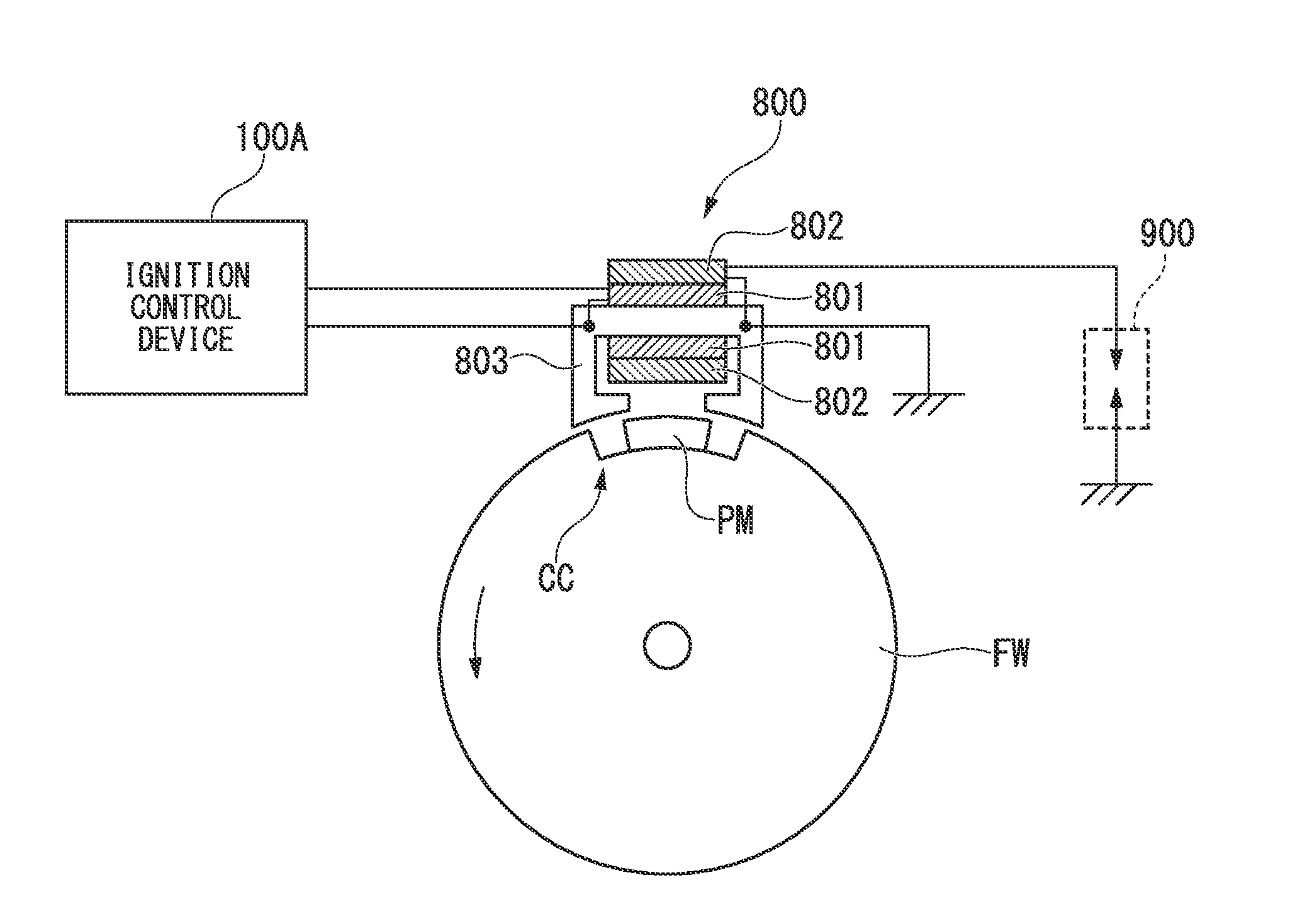
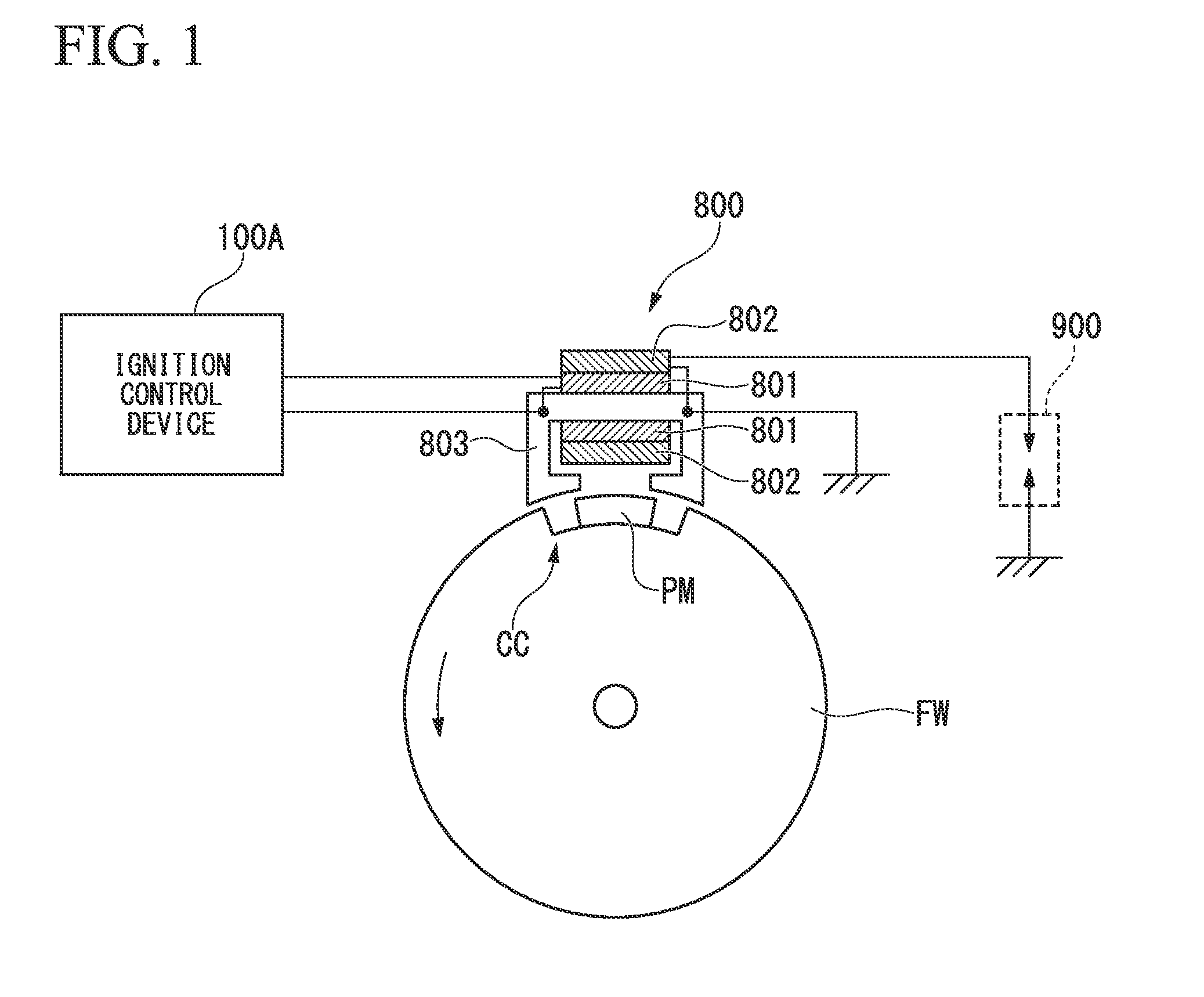
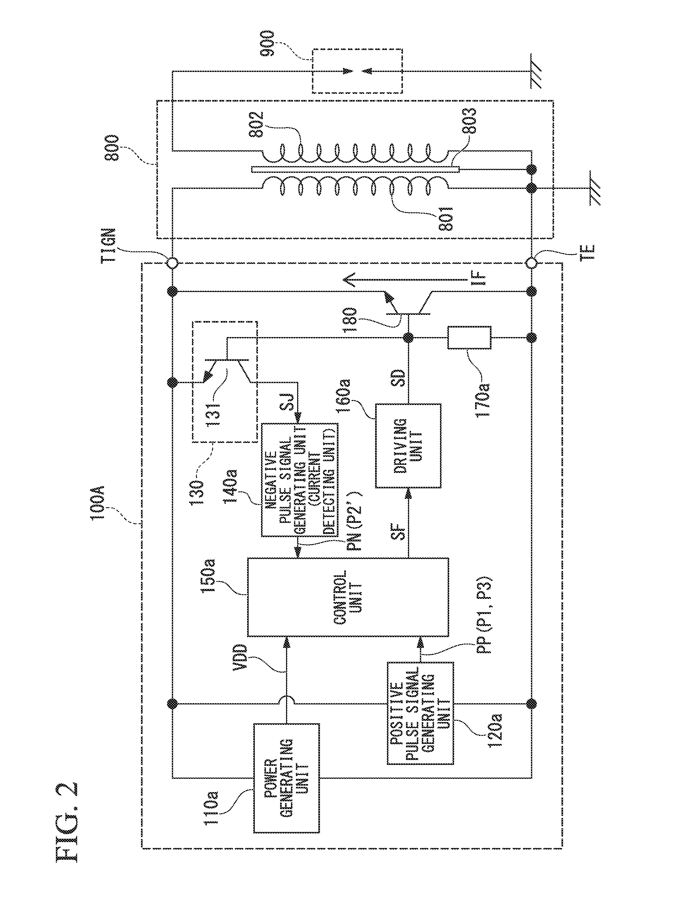
[0044]FIG. 1 is a diagram schematically showing an application example of an ignition control unit 100A according to a first embodiment of the present invention. The ignition control device 100A is connected to a primary winding 801 of an ignition coil 800 mounted on an internal combustion engine (not shown). A spark plug 900 is connected to a secondary winding 802 of the ignition coil 800. Both ends of a core 803 of the ignition coil 800 are disposed in proximity to an outer peripheral portion of a flywheel FW included in the internal combustion engine.

[0045]A recess CC is formed on the outer peripheral portion of the flywheel FW. The recessed portion CC is attached with a permanent magnet PM that generates a magnetic field to induce a pulse signal in the primary winding 801 of the ignition coil 800. When the flywheel FW attached with the permanent magnet PM is rotated, a change in magnetic flux in the core 803 of the ignition coil 800 causes first to th...

second embodiment

[0092]In the above-described first embodiment, it is assumed that a biased state of the switching element 180 is detected from the bias voltage of the npn-type transistor constituting the switching element 180, using the dummy transistor 131 of the state detecting unit 130. In the second embodiment of the present invention, it is detected from the direction of the current flowing through the primary winding 801 of the ignition coil 800 that the switching element 800 is biased into the on-state. For this purpose, the state detecting unit 130 includes, for example, a shunt resistor (not shown) inserted in the current path of the primary winding 801. Then, the state detecting unit 130 of the present embodiment determines a direction of the current flowing through the primary winding 801 from the terminal voltage of the shunt resistor, thereby detecting a biased state of the switching element 180 based on a result of the determination.

[0093]As described above, the biased state in which ...

third embodiment

Description of Configuration

[0098]FIG. 7 is a diagram schematically showing an application example of an ignition control device 100B according to the third embodiment of the present invention. The ignition control unit 100B is connected to the primary winding 801 of the ignition coil 800 mounted on the internal combustion engine (not shown). The spark plug 900 is connected to the secondary winding 802 of the ignition coil 800. Both ends of the core 803 of the ignition coil 800 are disposed in proximity to the outer peripheral portion of the flywheel FW provided in the internal combustion engine. The core 803 and the flywheel FW form a closed magnetic circuit.

[0099]The recess CC is formed on the outer peripheral portion of the flywheel FW. Additionally, the permanent magnet PM is mounted on the recessed portion CC. If the flywheel FW equipped with the permanent magnet PM is rotated, a change in magnetic flux in the core 803 of the ignition coil 800 causes, in each rotation cycle of ...


PUM


Abstract

An ignition control device according to one embodiment of the present invention is configured to, based on a pulse signal to be induced in an ignition coil in accordance with rotation of an internal combustion engine, cause a voltage to be supplied to an ignition plug included in the internal combustion engine, to be generated in the ignition coil. The ignition control device includes: a switching element configured to energize the ignition coil; a biasing unit configured to bias control terminals of the switching element so that the switching element is turned on when the pulse signal is induced; a state detecting unit configured to detect a biased state of the switching element; and a control unit configured to set a timing for controlling de-energization of the ignition coil in response to a result of detection performed by the state detecting unit, and to control the switching element to be turned off in accordance with the timing.

Description

TECHNICAL FIELD[0001]The present invention relates to an ignition control device and an ignition control method for an internal combustion engine. Particularly, the present invention relates to a technique for preventing erroneous ignition.[0002]Priority is claimed on Japanese Patent Application No. 2012-277123 filed Dec. 19, 2012, and Japanese Patent Application No. 2013-026086 filed Feb. 13, 2013, the content of which are incorporated herein by reference.BACKGROUND ART[0003]As an ignition control device for an internal combustion engine, there is an inductive-discharge-type (or current-shutdown-type) ignition control device requiring no external power source, such as a battery (Patent Document 1). According to the ignition control device, energization of an ignition coil (initiation and termination of energization) is controlled using a pulse induced in the ignition coil in accordance with rotation of the internal combustion engine. Then, a high voltage generated when the ignition...

Claims


Application Information

Patent Timeline
Patent Type & Authority Applications(United States)
IPC IPC(8): F02P3/045F02P7/077
CPCF02P7/077F02P3/0453F02P1/08F02P3/0407F02P7/07F02P1/083F02P5/1502F02P5/155F02P9/002Y02T10/40
Inventor TOJO, TOKUZO
Owner SHINDENGEN ELECTRIC MFG CO LTD
Why Eureka
Try Eureka