

Radio frequency coil device for magnetic resonance neck imaging
A technology of radio frequency coils and magnetic resonance, which is applied in the directions of magnetic resonance measurement, measuring devices, and measuring magnetic variables, etc. It can solve problems such as inability to place and reduce the clarity of magnetic resonance images, and achieve the effect of compact structure
- Summary
- Abstract
- Description
- Claims
- Application Information
AI Technical Summary
Problems solved by technology
Method used
Image

Examples
Embodiment 1
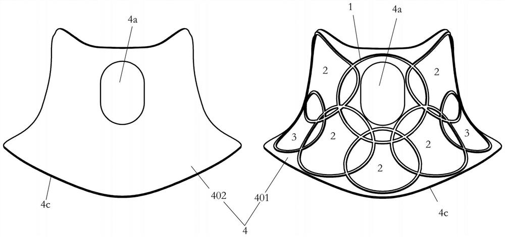
[0045] Figure 1 to Figure 3A specific embodiment of the radio frequency coil device for magnetic resonance neck imaging of the present application is shown, which includes a coil case 4 and 8 coil units arranged in the coil case, and these 8 coil units together form a 8-channel coil array. The coil case 4 not only serves as a carrier for each coil unit, carrying and fixing these coil units, but also serves as a protection body for each coil unit, protecting these coil units from external damage.
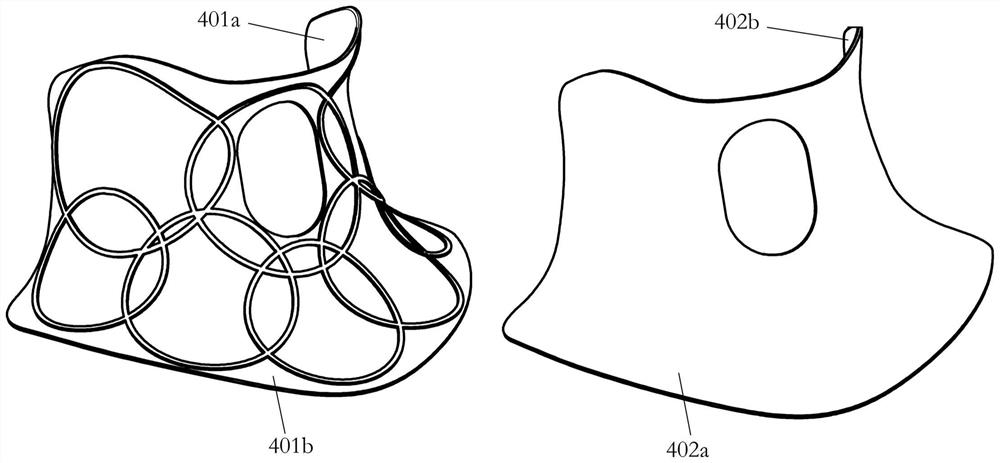
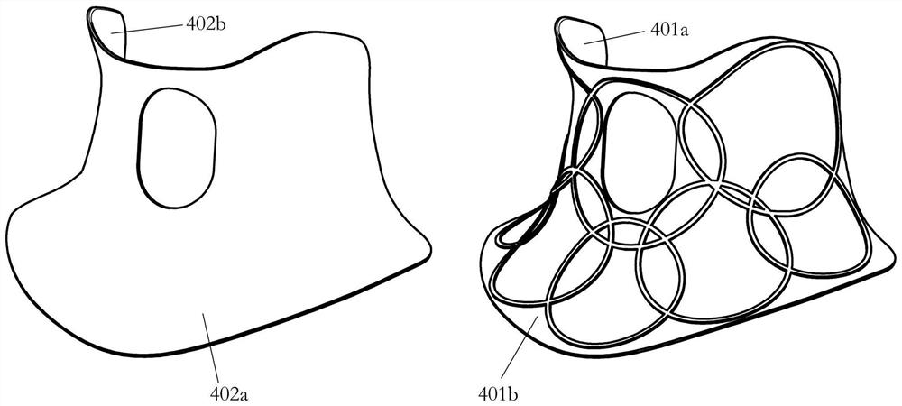
[0046] In order to allow the above-mentioned coil units to be as close as possible to the body of the examinee during the magnetic resonance examination, the present embodiment sets the coil case 4 and the coil unit in this way, specifically, the coil case 4 has: The matching inner curved surface 401a, the outer curved surface 402a facing away from the inner surface, is connected to the inner curved surface and the outer edge 4c at the periphery of the outer curved surface. The su...
Embodiment 2
[0059] Figure 5 to Figure 8 It shows the second specific embodiment of the radio frequency coil device for magnetic resonance neck imaging of the present application, its structure is similar to that of Embodiment 1, the main difference is:
[0060] In this embodiment, a total of 16 coil units are configured, and these 16 coil units together form a 16-channel coil array. The aforementioned 16 coil units are respectively 1 first coil unit 1 , 6 second coil units 2 , and 9 third coil units 3 . Wherein, the first coil unit 1 is arranged around the periphery of the Adam's apple hole 4a. The six second coil units 2 are partially overlapped in sequence along the circumferential direction of the Adam's apple hole 4a, and each second coil unit 2 not only partially overlaps with the first coil unit 1, but also abuts against the Adam's apple hole. 4a on the outside of the hole wall. Nine third coil units 3 are sequentially arranged overlapping along the circumferential direction of ...
Embodiment 3
[0069] Figure 7 It shows the third specific embodiment of the radio frequency coil device for magnetic resonance neck imaging of the present application. Unlike the above-mentioned embodiments 1 and 2, this embodiment does not have an Adam's apple hole on the coil shell. Instead, an Adam's apple opening 4b is provided on the outer edge 4c of the coil casing 4 for it. The role of the Adam's apple opening 4b is the same as that of the Adam's apple hole in Embodiments 1 and 2, both to provide free space for the examinee's Adam's apple, so that the coil shell 4 can better fit the examinee's skin, and It will not affect the feelings of the examinee too much.
[0070] After the Adam's apple hole is replaced by the Adam's apple opening 4b, the coil array structure of 8 channels and 16 channels can still be used. The disadvantage is that a part of the first coil unit will be exposed at the Adam's apple opening 4b. In order to eliminate the aforementioned disadvantages, in other imp...
PUM
 Abstract
Description
Claims
Application Information