Supercharge Your Innovation With Domain-Expert AI Agents!

Vehicle remote diagnosis system and method

A remote diagnosis and vehicle technology, which is applied in the field of vehicle remote diagnosis system, can solve problems such as unstable operation status, data loss, and inability to obtain correct diagnosis results on the remote diagnosis side, achieving the effect of improving stability and success rate

Active Publication Date: 2021-08-13
AUTEL INTELLIGENT TECHNOLOGY CORP LTD
View PDF8 Cites 1 Cited by
  • Summary
  • Abstract
  • Description
  • Claims
  • Application Information

AI Technical Summary

Problems solved by technology

[0004] At present, the remote VCI device is generally powered by a fixed power supply voltage, which will have the following adverse effects: when the operating state of the vehicle is unstable, for example, when the battery voltage of the vehicle drops and the operating state is unstable (the operating state is unstable It can be that the vehicle electronics cannot work normally due to unstable power supply), because the local VCI device is powered by the vehicle battery, the local VCI device will become unstable due to unstable power supply, and the remote VCI device communicates with the local VCI device Connection, when the local VCI device is unstable, the remote VCI device will also become unstable. At this time, when data transmission is performed between the local VCI device and the remote VCI device, data loss will occur, and in severe cases, the system may even crash Circumstances that cause remote diagnosis to fail
In addition, when performing remote diagnosis, the remote diagnosis side does not know the real-time running state of the vehicle. If the real-time running state of the vehicle changes, the remote diagnosis side still performs programming according to the normal situation of the real-time running state of the vehicle. diagnosis, then the remote diagnosis side may not be able to obtain correct diagnosis results

Method used


Image

  • Vehicle remote diagnosis system and method
  • Vehicle remote diagnosis system and method
  • Vehicle remote diagnosis system and method

Examples


Embodiment Construction

[0043] In order to facilitate the understanding of the present application, the present application will be described in more detail below in conjunction with the accompanying drawings and specific implementation methods. It should be noted that when an element is described as being “connected” to another element, it may be directly connected to the other element, or there may be one or more intervening elements therebetween. In addition, the terms "first", "second", etc. are used for descriptive purposes only, and should not be construed as indicating or implying relative importance.

[0044] Unless otherwise defined, all technical and scientific terms used in this specification have the same meaning as commonly understood by one of ordinary skill in the technical field of the invention. The terminology used in the description of the present invention is only for the purpose of describing specific embodiments, and is not used to limit the present invention. The term "and / or"...


PUM


Abstract

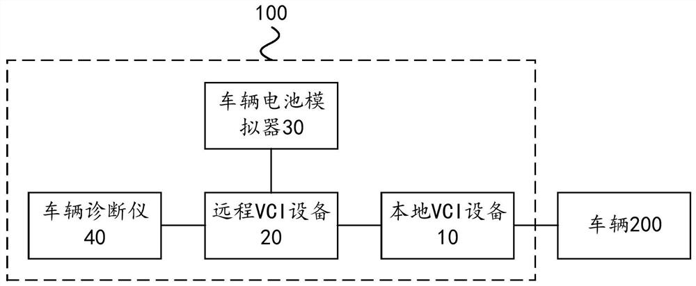
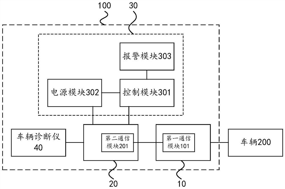
The embodiment of the invention relates to the technical field of vehicle diagnosis, and discloses a vehicle remote diagnosis system and method. The vehicle remote diagnosis system comprises local VC I equipment, remote VC I equipment, a vehicle battery simulator and a vehicle diagnosis instrument, wherein the local VC I equipment is connected with a vehicle, the remote VC I equipment is in communication connection with the local VC I equipment, the vehicle battery simulator is connected with the remote VC I equipment, the vehicle battery simulator can simulate the battery voltage of the vehicle to supply power to the remote VC I equipment, the vehicle diagnosis instrument is connected with the remote VC I equipment, and the vehicle diagnosis instrument can send a diagnostic command to the vehicle through the remote VC I equipment and the local VC I equipment so as to obtain diagnostic data fed back by the vehicle based on the diagnostic command. The remote VC I equipment is powered by simulating the battery voltage of the vehicle, so that the stability and success rate of remote diagnosis of the vehicle can be improved.

Description

technical field [0001] The invention relates to the technical field of vehicle diagnosis, in particular to a vehicle remote diagnosis system and method. Background technique [0002] Vehicle remote diagnosis refers to vehicle diagnostic equipment. For example, a vehicle diagnostic instrument communicates with the vehicle's ECU (Electronic Control Unit) through a communication interface device, and then sends a diagnostic command to the vehicle's ECU to obtain feedback from the vehicle's ECU based on the diagnostic command. How the diagnostic data is diagnosed. The vehicle diagnostic instrument can analyze the fault information of the vehicle according to the diagnostic data, so that professionals can repair the vehicle in time when it is determined that the vehicle is faulty. Since this diagnosis method does not require close contact with the vehicle, it is more convenient and efficient. [0003] Traditional remote diagnosis systems generally include local VCI equipment (V...

Claims


Application Information

Patent Timeline
IPC IPC(8): G05B23/02
CPCG05B23/0213Y02T90/16G05B23/0237G01R31/3835G06F30/20G07C5/008G07C5/0833
Inventor 王永超
Owner AUTEL INTELLIGENT TECHNOLOGY CORP LTD
Features
  • R&D
  • Intellectual Property
  • Life Sciences
  • Materials
  • Tech Scout
  • Unparalleled Data Quality
  • Higher Quality Content
  • 60% Fewer Hallucinations
Learn More