Gear switch pin rotating device and pin rotating machining method

A gear switch and turning foot technology, applied in the direction of electrical switches, electrical components, circuits, etc., can solve the problems of processing errors and insufficient transmission reliability, and achieve the effect of ensuring processing quality, ensuring the processing effect of rotating feet, and low structural cost.

Pending Publication Date: 2021-08-13
HUAIYIN INSTITUTE OF TECHNOLOGY
View PDF2 Cites 0 Cited by
  • Summary
  • Abstract
  • Description
  • Claims
  • Application Information

AI Technical Summary

Problems solved by technology

Although the device in this application can realize the bending processing of multiple pins at one time, the driving force is completed by gear transmission during the processing process. When processing multiple pins at the same time, the transmission reliability of the device is insufficient, and processing errors are prone to occur. Happening

Method used


Image

  • Gear switch pin rotating device and pin rotating machining method
  • Gear switch pin rotating device and pin rotating machining method
  • Gear switch pin rotating device and pin rotating machining method

Examples


Embodiment 1

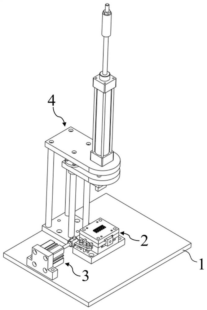
[0074] The gear switch foot rotation device of this embodiment includes,

[0075] Bottom plate 1,

[0076] The swivel unit 2 and the drive unit 3 fixed on the bottom plate 1;

[0077] The swivel unit 2 includes,

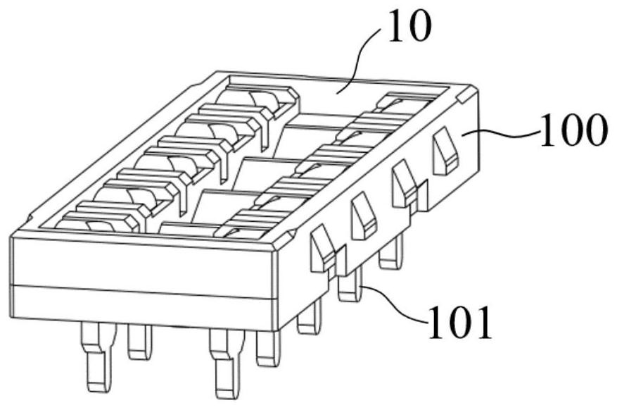
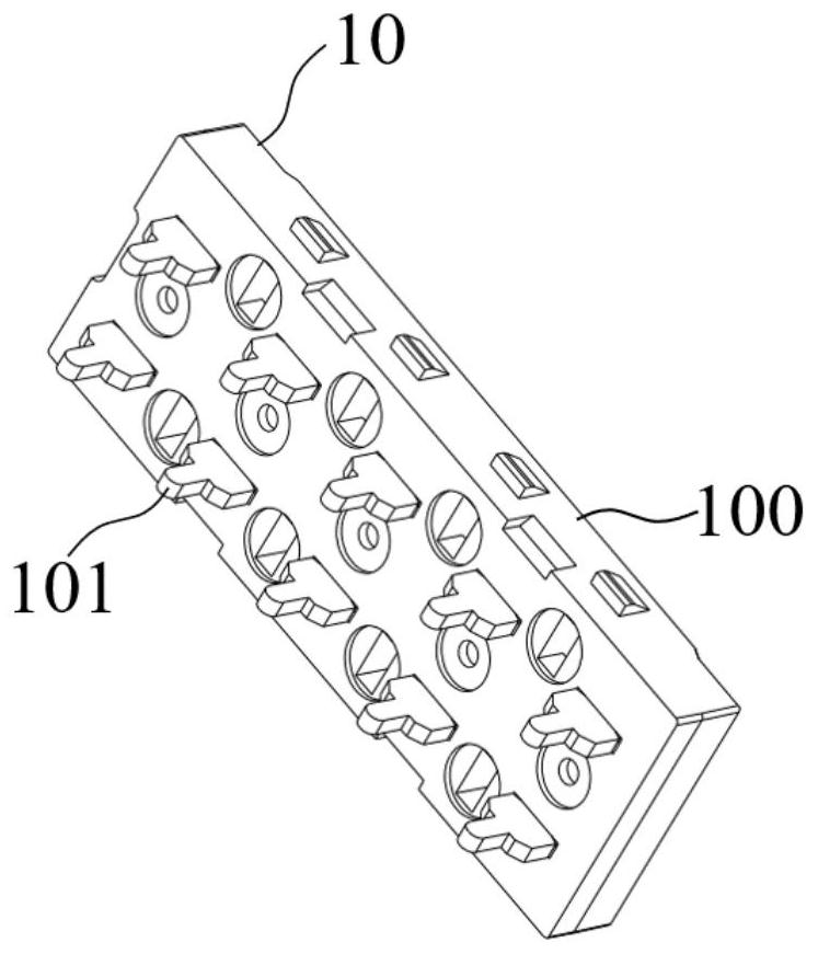
[0078] The workpiece mounting plate 20 is provided with a mounting groove 200 matching the gear switch 10, and a plurality of relief holes 201 are provided through the mounting groove 200 for the pins 101 of the gear switch 10 to protrude;

[0079] There are several swivel legs 21, which are correspondingly located below each relief hole 201. The top surface of the swivel leg 21 is provided with an assembly hole 210 matching the shape of the pin 101. The side of the swivel leg 21 is horizontally formed with a transmission rod 211, each The swivel legs 21 are arranged in two rows, and the transmission rods 211 of the two rows of swivel legs 21 are facing oppositely;

[0080] There are two driving rods 22, which are arranged horizontally on both sides of the swivel ...

Embodiment 2

[0091]The gear switch foot rotation device of this embodiment is further improved on the basis of Embodiment 1, and the bottom mounting block 23 is connected to the bottom plate 1 through the base plate 24 arranged below it;

[0092] The telescopic rod 31 of the drive unit 3 is transmission-connected with the drive pull rod 22 through the reversing drive mechanism 25; the reversing drive mechanism 25 includes:

[0093] Rotating rod 250, which is horizontally arranged between the driving rod 22 and the driving cylinder 1 30, one end of the rotating rod 250 corresponds to the two driving rods 22, and the other end corresponds to the telescopic rod 31;

[0094] Fixed turn pin 251, it is vertically arranged, and the bottom end is connected to the base plate 24 places between driving cylinder one 30 and bottom mounting block 23;

[0095] Waist-shaped hole 1 252, which is provided with two places on the rotating rod 250 corresponding to the positions of the two driving rods 22, and ...

Embodiment 3

[0105] The gear switch foot rotation device of this embodiment is further improved on the basis of Embodiments 1 and 2, and the bottom mounting block 23 includes:

[0106] Mounting hole one 230, which corresponds to the bottom position of each swivel foot 21, is opened on the top surface of the bottom mounting block 23, and the swivel leg 21 is rotationally connected with the bottom mounting block 23 through the mounting hole one 230;

[0107] The guide slots 231 corresponding to the positions of the driving rods 22 are opened on both sides of the installation hole 1 230, and limit the movement of the driving rods 22 along their lengthwise directions.

[0108] Such as Figure 5 and Figure 8 As shown, the mounting hole 1 230 on the top surface of the bottom mounting block 23 is used to limit the bottom of each swivel foot 21, and the guide groove 231 is used to limit and guide the movement of the driving rod 22. Through this embodiment The design of this device makes the mov...


PUM


Abstract

The invention discloses a gear switch pin rotating device and a pin rotating machining method, and belongs to the field of pin machining equipment. The device comprises a bottom plate, a pin rotating unit and a driving unit. The pin rotating unit comprises a workpiece mounting plate, rotating feet, driving pull rods, and a bottom mounting block. A mounting groove is formed in the workpiece mounting plate, and a plurality of receding holes are formed in the mounting groove in a penetrating mode; the rotating feet are correspondingly arranged below the receding holes, assembling holes are formed in the top faces of the rotating feet, and transmission rods are formed on the side faces of the rotating feet; the driving pull rods are horizontally arranged on the two sides of the rotating feet, mounting positions are arranged on the driving pull rods, and the mounting position of each driving pull rod is in transmission connection with the corresponding column of transmission rods; and the bottom mounting block is arranged below the rotating feet, and the bottoms of the rotating feet are rotationally connected with the bottom mounting block. The driving unit is in transmission connection with the driving pull rods and provides driving force for the driving pull rods to move in the length direction. Through all structures of the pin rotating unit, under the driving of the driving unit, all pins of the gear switch can be subjected to unified rotating machining, the machining efficiency is high, pin rotating is consistent, and the machining quality is ensured.

Description

technical field [0001] The invention belongs to the technical field of pin processing equipment, and more specifically relates to a gear switch swivel device and a swivel processing method. Background technique [0002] The heat gun is one of the tools commonly used for repairing circuit boards such as mobile phones. It is mainly used to heat and desolder the components on the PCB circuit board for replacement. Different circuit boards and different solders have different temperature requirements, so The heat gun needs to be equipped with a thermostat switch to control the heating temperature range, and a gear switch is required to realize this function. [0003] Not only heat guns, but also gear switches are used to adjust the gears of many equipments. The number of gears of the gear switches often determines the performance and price of the corresponding equipment; there are many kinds of gear switches, such as Two gears with four legs, three gears with six legs, four gea...

Claims


Application Information

Patent Timeline
Patent Type & Authority Applications(China)
IPC IPC(8): H01H11/00B21F1/00
CPCB21F1/00H01H11/00
Inventor 董育伟刘宬邑曹博文谢小龙刘林海
Owner HUAIYIN INSTITUTE OF TECHNOLOGY
Why Eureka
Try Eureka