High Power Microwave Ring Focus Dual Reflector Antenna

Active Publication Date: 2021-11-23
NAVAL UNIV OF ENG PLA
View PDF18 Cites 0 Cited by
  • Summary
  • Abstract
  • Description
  • Claims
  • Application Information

AI Technical Summary

Problems solved by technology

[0003] However, when the above-mentioned high-power antennas achieve high gain, the structure is usually relatively complex or requires high processing accuracy, and none of the antenna folding schemes have been proposed to make the structure compact

Method used


Image

  • High Power Microwave Ring Focus Dual Reflector Antenna
  • High Power Microwave Ring Focus Dual Reflector Antenna
  • High Power Microwave Ring Focus Dual Reflector Antenna

Examples


Embodiment Construction

[0056] The present invention will be further described in detail below in conjunction with the accompanying drawings and specific examples.

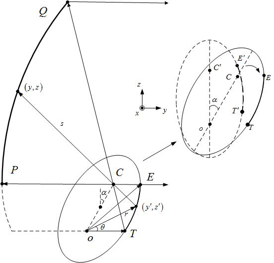
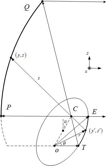
[0057] High Power Microwave Ring Focus Dual-Reflector Antenna including TEM (Transverse Electromagnetic Mode) Coaxially Connected to Microwave Source - Circular WaveguideTM 01 (transverse magnetic wave 01 mode) mode converter, secondary reflector, main reflector and horn antenna, the secondary reflector is set opposite to the main reflector. The inner and outer radii of the input port of the mode converter are consistent with the microwave source to maintain good impedance matching; the output end of the mode converter is connected to the horn antenna, which utilizes the high directivity and symmetry of the horn antenna; the sub-reflector is an ellipsoid, composed of The ellipse ET segment rotates around the OT axis (y-axis) for one cycle. The sub-reflector contains focus O and focus C. The phase center of the horn antenna is located at ...


PUM


Abstract

The invention discloses a high-power microwave ring-focus double-reflector antenna, which includes a TEM-circular waveguide TM coaxially connected with a microwave source 01 mode converter, sub-reflector, main reflector and horn antenna, the sub-reflector is set opposite to the main reflector; the output end of the mode converter is connected to the horn antenna, and the inner and outer radii of the input port of the mode converter are in line with the microwave source Consistent; the sub-reflector is an ellipsoid, and the ellipse ET section rotates around the OT axis for one circle. The sub-reflector includes focus O and focus C. The phase center of the horn antenna is located at the focus O of the sub-reflector. The main reflector is a parabolic ring The surface is rotated around the OT axis by the parabola PQ section, and the focal point of the main reflector coincides with the focus C of the secondary reflector. The ring-focus double-reflector antenna is directly connected to the microwave source to achieve high gain. A coaxial mode converter is designed between the horn antenna and the microwave source to make full use of the axial space to make the structure compact, and finally realize the directional radiation concentrated in the axial direction.

Description

technical field [0001] The invention relates to the technical field of high-power microwave antennas, in particular to a high-power microwave ring-focus double-reflector antenna. Background technique [0002] In order to enhance the radiation effect of high-power microwaves, high-power microwave antennas usually have a higher gain. There are two types of typical high-gain high-power microwave antennas: reflector antennas, such as Vlasov antennas with secondary reflectors, large-aperture COBRA antennas (DOI: CNKI: CDMD: 2.2006.113371), etc.; Microwave Dense Slot Waveguide Antenna (Application No. 201610436530.X), High Power Microwave Suspension Plate Array Antenna (DOI: 10.1063 / 1.5110732), etc. At the same time, the microwave mode output by most microwave sources is a rotationally symmetric mode (such as an axial TEM), and it is usually necessary to design a mode converter to convert the rotationally symmetric mode into a mode that is easy to directional radiation (such as a...

Claims


Application Information

Patent Timeline
Patent Type & Authority Patents(China)
IPC IPC(8): H01Q1/50H01Q13/02H01Q1/00H01Q19/19H01Q23/00
CPCH01Q1/00H01Q1/50H01Q13/02H01Q19/19H01Q23/00
Inventor 罗康孟进朱丹妮袁玉章王海涛黄立洋张嘉毫向中武
Owner NAVAL UNIV OF ENG PLA
Why Eureka
Try Eureka