Shaping sucking device for edge band
A suction device and edge banding technology are applied in the directions of cleaning methods, cleaning methods and utensils, chemical instruments and methods using gas flow, etc. simple effect
- Summary
- Abstract
- Description
- Claims
- Application Information
AI Technical Summary
Problems solved by technology
Method used
Image


Examples
Embodiment 1
[0029] In order to quickly and accurately adjust the position of the shaping plate 3, several guide grooves 21 are arranged side by side on the upper end surface of the main seat plate 2, and the lower side of the shaping plate 3 is provided with a guide groove embedded in the guiding groove 21. The slider 31, the guide groove 21 communicates with the air suction channel, the guide groove 21 can not only guide the movement of the shaping plate 3, but also can play the role of an air suction port to expand the range of air suction.
[0030] As a preferred shape of the guide groove 21, the cross-sectional shape of the guide groove 21 is cross-shaped or T-shaped, such as figure 2 As shown, the cross-shaped guide groove 21 has a better guiding effect.
Embodiment 2
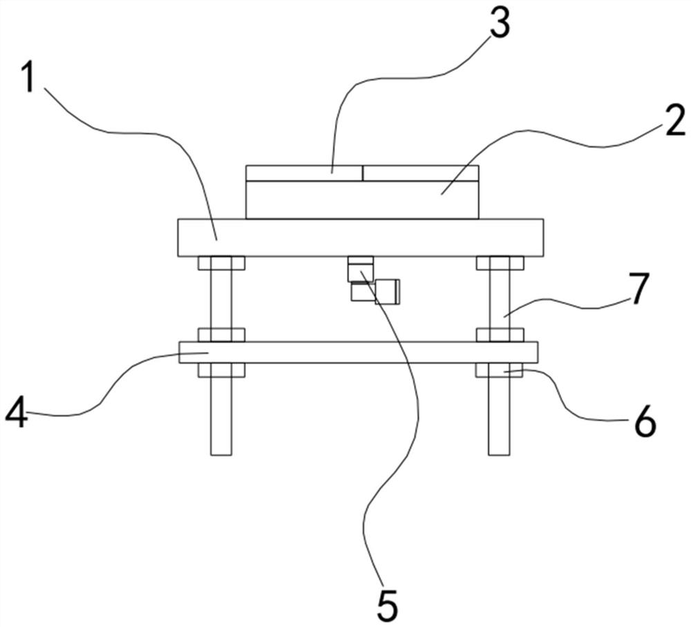
[0032] The air suction channel includes an air suction connection hole 11 that runs through the substrate 1 and corresponds to the air suction valve 5 one-to-one, and an air suction bottom hole 23 that is arranged at the bottom of the shaping plate 3 and communicates with the air suction connection hole 11 correspondingly. The upper end of the suction bottom hole 23 communicates with at least one guide groove 21, and the lower end of the suction connection hole 11 is connected with the suction valve 5. Through the communication between the suction connection hole 11 and the suction bottom hole 23, it can realize The inspiratory pathway is connected.
[0033] In order to improve the range of suction and the strength of suction, the two suction valves 5 are arranged side by side, and the upper end of the suction bottom hole 23 communicates with several guide grooves 21 through the transverse passage 22. All the guide grooves 21 can be communicated through the transverse channel ...
Embodiment 3
[0035] In order to install the suction device firmly and stably, a mounting plate 4 is arranged laterally below the base plate 1, and mounting screws 7 passing through the mounting plate 4 are vertically arranged at the top corners of the lower end of the base plate 1. Lock nuts 6 located on the upper and lower sides of the mounting plate 4 are set on the screw 7 of the mounting plate 4. By adjusting the distance between the mounting plate 4 and the base plate 1, the whole device is clamped on the transmission track of the edge banding strip to adapt to different installation environment.
PUM
 Abstract
Description
Claims
Application Information
 - Generate Ideas
- Intellectual Property
- Life Sciences
- Materials
- Tech Scout
- Unparalleled Data Quality
- Higher Quality Content
- 60% Fewer Hallucinations
Browse by: Latest US Patents, China's latest patents, Technical Efficacy Thesaurus, Application Domain, Technology Topic, Popular Technical Reports.
© 2025 PatSnap. All rights reserved.Legal|Privacy policy|Modern Slavery Act Transparency Statement|Sitemap|About US| Contact US: help@patsnap.com