Wind-spot-resistant glass tempering equipment and working method thereof
A glass tempering and equipment technology, applied in glass tempering, glass manufacturing equipment, manufacturing tools, etc., can solve problems such as energy consumption, poor practicability, glass melting, etc., to avoid high temperature melting, improve practicability, and stabilize air supply Effect
- Summary
- Abstract
- Description
- Claims
- Application Information
AI Technical Summary
Problems solved by technology
Method used
Image
Examples
Example Embodiment
[0044] Example 1
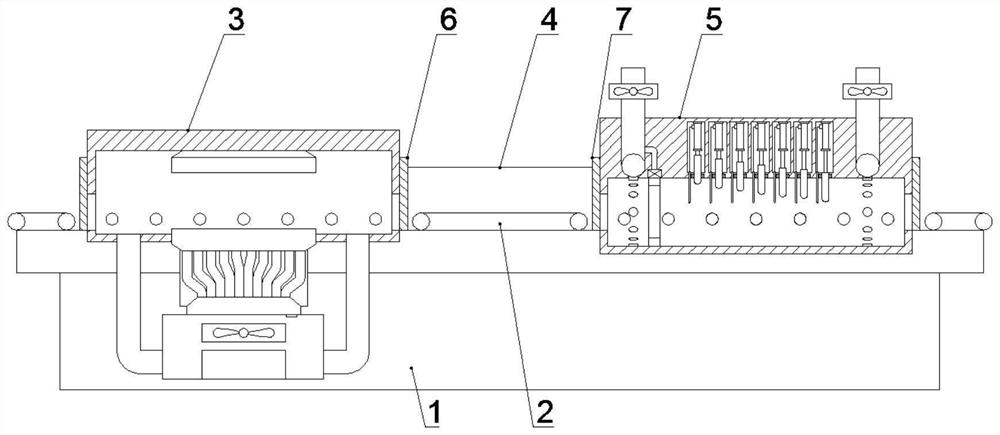
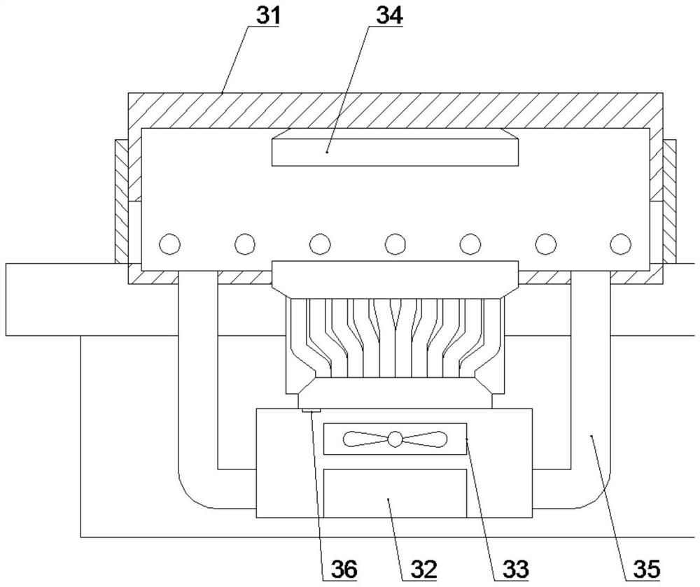
[0045] like Figure 1-5 The anti-wind spot glass tempering equipment shown includes: a base 1, a conveyor belt 2, a heating and heat preservation bin 3, a connecting cover 4, a wind tunnel cooling bin 5, a first isolation door 6 and a second isolation door 7, the The top of the base 1 is provided with a heating insulation bin 3, the output end of the heating insulation bin 3 is connected with a connection cover 4, and the output end of the connection cover 4 is connected with a pneumatic cooling bin 5; the top of the base 1 is provided with a There is a conveyor belt 2, and the conveyor belt 2 is arranged in the heating and heat preservation bin 3, and the conveyor belt 2 is arranged in the fan cooling bin 3; the input end of the connecting cover 4 is provided with a first isolation door 6, and the connecting The output end of the cover 4 is provided with a second isolation door 7 .
[0046] The heating and heat preservation bin 3 described in this embodim...
Example Embodiment
[0061] Example 2
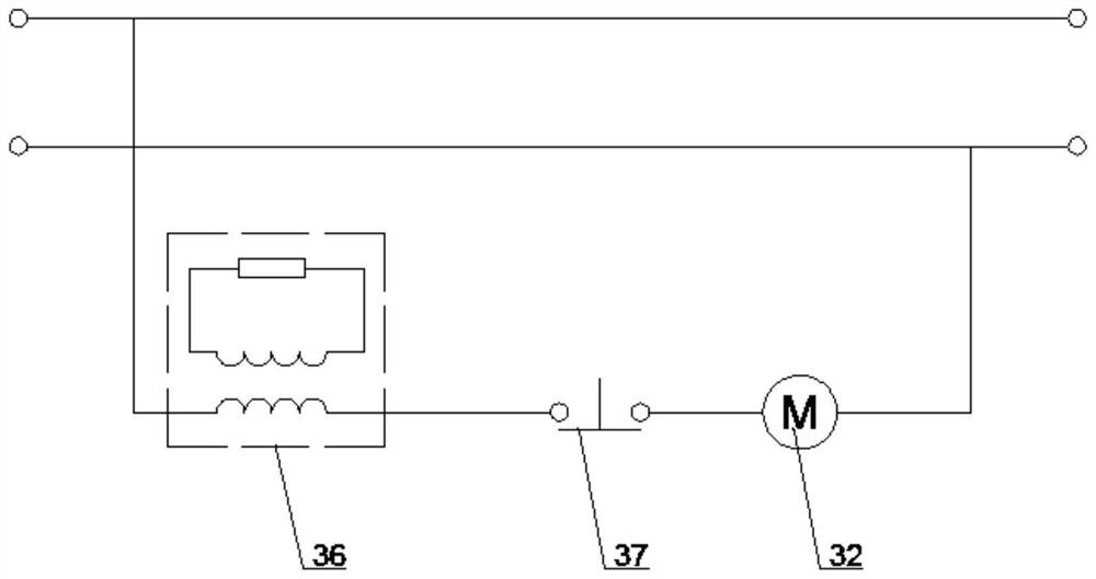
[0062] like Figure 1-3 The anti-wind spot glass tempering equipment shown includes: a base 1, a conveyor belt 2, a heating and heat preservation bin 3, a connecting cover 4, a wind tunnel cooling bin 5, a first isolation door 6 and a second isolation door 7, the The top of the base 1 is provided with a heating insulation bin 3, the output end of the heating insulation bin 3 is connected with a connection cover 4, and the output end of the connection cover 4 is connected with a pneumatic cooling bin 5; the top of the base 1 is provided with a There is a conveyor belt 2, and the conveyor belt 2 is arranged in the heating and heat preservation bin 3, and the conveyor belt 2 is arranged in the fan cooling bin 3; the input end of the connecting cover 4 is provided with a first isolation door 6, and the connecting The output end of the cover 4 is provided with a second isolation door 7 .
[0063] The heating and heat preservation bin 3 described in this embodim...
Example Embodiment
[0066] Example 3
[0067] like figure 1 and 4 The anti-wind spot glass tempering equipment shown includes: a base 1, a conveyor belt 2, a heating and heat preservation bin 3, a connecting cover 4, a wind tunnel cooling bin 5, a first isolation door 6 and a second isolation door 7, the The top of the base 1 is provided with a heating insulation bin 3, the output end of the heating insulation bin 3 is connected with a connection cover 4, and the output end of the connection cover 4 is connected with a pneumatic cooling bin 5; the top of the base 1 is provided with a There is a conveyor belt 2, and the conveyor belt 2 is arranged in the heating and heat preservation bin 3, and the conveyor belt 2 is arranged in the fan cooling bin 3; the input end of the connecting cover 4 is provided with a first isolation door 6, and the connecting The output end of the cover 4 is provided with a second isolation door 7 .
[0068] The wind tunnel cooling chamber 5 described in this embodimen...
PUM
 Abstract
Description
Claims
Application Information
 - R&D
- Intellectual Property
- Life Sciences
- Materials
- Tech Scout
- Unparalleled Data Quality
- Higher Quality Content
- 60% Fewer Hallucinations
Browse by: Latest US Patents, China's latest patents, Technical Efficacy Thesaurus, Application Domain, Technology Topic, Popular Technical Reports.
© 2025 PatSnap. All rights reserved.Legal|Privacy policy|Modern Slavery Act Transparency Statement|Sitemap|About US| Contact US: help@patsnap.com


