Multi-unmanned aerial vehicle system formation tracking control method based on dynamic event triggering

An event-triggered, multi-UAV technology, applied in the control field, can solve the problem of not considering the leader's time-varying formation consistency, and achieve the effects of reducing event triggering, saving energy, and improving communication efficiency

Active Publication Date: 2021-08-17
SHANDONG UNIV
View PDF8 Cites 5 Cited by
  • Summary
  • Abstract
  • Description
  • Claims
  • Application Information

AI Technical Summary

Problems solved by technology

Literature "S.Du, T.Liu, W.Daniel, Dynamic event-triggered control for leader-following consensus of multiagent systems, IEEE Transactions on SystemsMan and Cybernetics-Systems, 50(9):3243-3251, 2020" and literature " The use of internal dynamic A dynamic event-triggered scheme that improves communication efficiency with variables, which can further filter out unnecessary event triggers, but does not consider the time-varying formation consistency of the leader with bounded inputs

Method used


Image

  • Multi-unmanned aerial vehicle system formation tracking control method based on dynamic event triggering
  • Multi-unmanned aerial vehicle system formation tracking control method based on dynamic event triggering
  • Multi-unmanned aerial vehicle system formation tracking control method based on dynamic event triggering

Examples


Embodiment 1

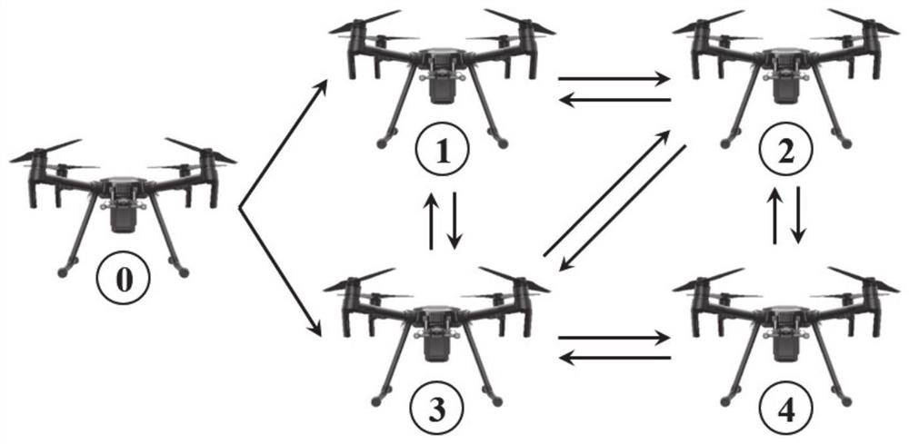
[0048] In a typical implementation of the present application, such as figure 1 As shown, taking the UAVs system composed of five UAVs as an example, the UAV numbered 0 can exist as a virtual UAV as the leader in the UAVs system, and the other UAVs numbered 1-4 are followers. The position information of the UAV numbered 0 can be transmitted to the UAVs numbered 1 and 3, and the position status of the UAVs numbered 1-4 can be transmitted to each other. A UAV formation control method based on dynamic event triggering of the present invention mainly includes parameter initialization, state estimation during no trigger period, calculation of event trigger function and dynamic threshold, judging whether the trigger condition is reached, communication and state update according to the trigger situation.

[0049] This embodiment discloses a UAVs system formation control method based on dynamic event triggering, and the specific steps include:

[0050] Step 1: Mathematically model th...

Embodiment 2

[0104] The purpose of this embodiment is to provide a computing device, including a memory, a processor, and a computer program stored in the memory and operable on the processor, and the processor implements the steps of the above method when executing the program.

Embodiment 3

[0106] The purpose of this embodiment is to provide a computer-readable storage medium.

[0107] A computer-readable storage medium, on which a computer program is stored, and when the program is executed by a processor, the steps of the above-mentioned method are executed.


PUM


Abstract

The invention provides a multi-unmanned aerial vehicle system formation tracking control method based on dynamic event triggering. The method comprises the steps that mathematical modeling is carried out on a multi-agent system composed of multiple unmanned aerial vehicles; based on the established model, the state of the multi-agent is estimated in a non-triggering period, and based on an estimated value and a measured value, a measurement error is calculated and a tracking error is defined; based on the measurement error and the tracking error, a controller for formation compensation input and leader bounded control input compensation and dynamic event trigger functions are constructed, and a leader and a follower correspond to different dynamic event trigger functions; and when a first trigger function meets a trigger condition, the leader unmanned aerial vehicle communicates with the adjacent follower, and when the second trigger function meets the trigger condition, the unmanned aerial vehicle as the follower performs information communication with the adjacent follower. According to the method, a novel event triggering mechanism which saves more energy is designed by introducing auxiliary parameters, and the communication efficiency is remarkably improved.

Description

technical field [0001] The present disclosure belongs to the technical field of control, and in particular relates to a method and system for unmanned aerial vehicle formation control based on dynamic event triggering. Background technique [0002] The statements in this section merely provide background information related to the present disclosure and do not necessarily constitute prior art. [0003] UAV (unmanned aerial vehicle, UAV) has gradually occupied an important position in the military and civilian fields in recent years. Due to its flexible control, high-altitude operation, lightness and convenience, it is widely used in many missions, and has a wide range of applications. The prospect of application development is highly valued by countries all over the world. With the increasing complexity of the UAV flight environment and the improvement of UAV performance requirements, it has become an inevitable trend for multiple UAVs to cooperate in a time-varying formati...

Claims


Application Information

Patent Timeline
Patent Type & Authority Applications(China)
IPC IPC(8): G05D1/10
CPCG05D1/104
Inventor 魏爱荣岳露牟瑞
Owner SHANDONG UNIV
Why Eureka
Try Eureka