Tunable decoupling network for multi-antenna system

A multi-antenna system and decoupling network technology, applied in the field of tunable decoupling network, to achieve the effect of reducing complexity, realizing miniaturization and broadband performance, and high tunability

Active Publication Date: 2021-08-17
NINGBO UNIV
View PDF11 Cites 0 Cited by
  • Summary
  • Abstract
  • Description
  • Claims
  • Application Information

AI Technical Summary

Problems solved by technology

In this structure, by adding an auxiliary tunable unit composed of the fourth electronic device and the fifth electronic device in the tunable decoupling network, the coupling problem between non-adjacent antennas caused by the small size of the multi-antenna system can be solved, In this way, the decoupling function between any antennas in the multi-antenna system can be realized, which can meet the decoupling requirements of future multi-antenna system applications

Method used


Image

  • Tunable decoupling network for multi-antenna system
  • Tunable decoupling network for multi-antenna system
  • Tunable decoupling network for multi-antenna system

Examples


Embodiment 1

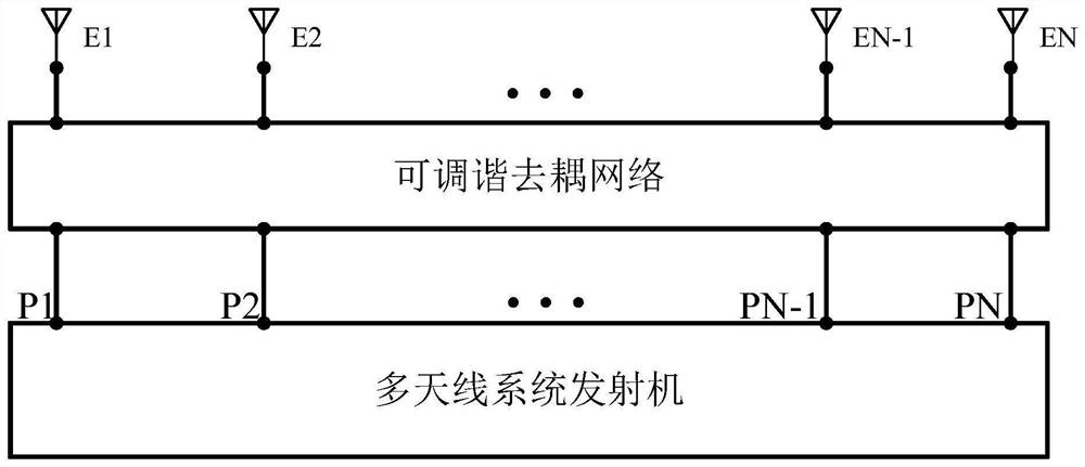
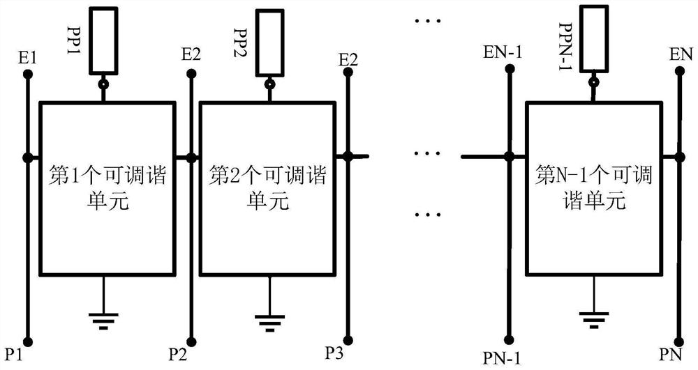
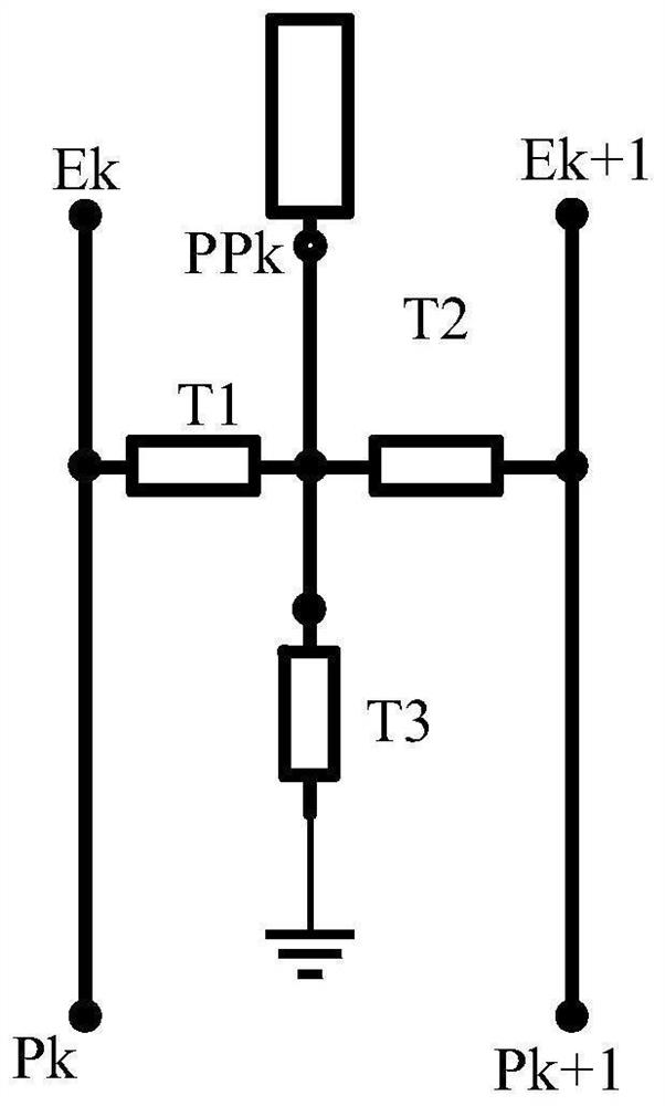
[0015] Embodiment one: if figure 1 , figure 2 with image 3 As shown, a tunable decoupling network for a multi-antenna system, including a tunable circuit and N-1 parasites PP1~PP(N-1), N is equal to the number of antennas in a multi-antenna system, N≥2 , the multi-antenna system has N antennas, the input end of the first antenna is used as the mth input end Em of the multi-antenna system, m=1, 2,..., N, the transmitter has N output ends connected to the multi-antenna system P1-PN, the tunable circuit is composed of N-1 tunable units, each tunable unit includes a first electronic device T1, a second electronic device T2 and a third electronic device T3, the first electronic device T1, the second The electronic device T2 and the third electronic device T3 are any one of the tunable capacitor and the tunable inductance respectively, one end of the first electronic device T1 is used as the first connection end of the tunable unit, and the other end of the first electronic devi...

Embodiment 2

[0021] Embodiment two: if figure 1 , figure 2 with image 3 As shown, a tunable decoupling network for a multi-antenna system, including a tunable circuit and N-1 parasites PP1~PP(N-1), N is equal to the number of antennas in a multi-antenna system, N≥2 , the multi-antenna system has N antennas, the input end of the first antenna is used as the mth input end of the multi-antenna system, m=1, 2,..., N, the transmitter has N output ends P1 connected to the multi-antenna system -PN, the tunable circuit is composed of N-1 tunable units, each tunable unit includes the first electronic device T1, the second electronic device T2 and the third electronic device T3, the first electronic device T1, the second electronic device The device T2 and the third electronic device T3 are any one of the tunable capacitor and the tunable inductance respectively, one end of the first electronic device T1 is used as the first connection end of the tunable unit, the other end of the first electron...


PUM


Abstract

The invention discloses a tunable decoupling network for a multi-antenna system, and the network comprises a tunable circuit and N-1 parasitic bodies, wherein N is equal to the number of antennas in the multi-antenna system, the tunable circuit is composed of N-1 tunable units, each tunable unit comprises three electronic devices, the three electronic devices are tunable capacitors or tunable inductors, one end of the first electronic device serves as a first connecting end of the tunable unit, the other end of the first electronic device, one end of the second electronic device and one end of the third electronic device are connected, and the connecting ends of the first electronic device, the second electronic device and the third electronic device serve as a second connecting end of the tunable unit; the other end of the second electronic device is a third connecting end of the tunable device, the other end of the third electronic device is grounded, the second connecting ends of the N-1 tunable units are connected with one ends of the N-1 parasitic bodies in a one-to-one correspondence manner, and every two adjacent antennas are correspondingly connected with the transmitter through one tunable unit; the advantages are that the miniaturized requirement is satisfied, and the decoupling bandwidth and the decoupling frequency are relatively wide.

Description

technical field [0001] The invention relates to a tuneable decoupling network, in particular to a tuneable decoupling network for a multi-antenna system. Background technique [0002] With the development of wireless communication technology in the direction of diversification, broadband, integration and intelligence, mobile data traffic is showing explosive growth. A Multiple-Input Multiple-Output (Multiple-Input Multiple-Output, MIMO) technology is a communication technology that can effectively improve wireless communication capacity and spectrum utilization. In order to implement MIMO technology in modern wireless communication systems, it is necessary to configure a multi-antenna system consisting of multiple antennas on the mobile terminal of the wireless communication system, and the transmitter of the mobile terminal transmits signals through multiple antennas. Under the requirements of multi-functional integration, mobile terminals not only need to widely support m...

Claims


Application Information

Patent Timeline
Patent Type & Authority Applications(China)
IPC IPC(8): H01Q21/00H01Q23/00
CPCH01Q21/00H01Q23/00
Inventor 陈益华昌洲陆云龙徐俊黄季甫
Owner NINGBO UNIV
Why Eureka
Try Eureka