

Rotor iron core stacking die
A rotor core and mold technology, which is applied in the manufacture of stator/rotor body, etc., can solve the problems of difficult control of rotor core size, looseness, insufficient pressing force of iron core punching, etc., and achieve good stacking quality and positioning process Simple, good positioning effect
- Summary
- Abstract
- Description
- Claims
- Application Information
AI Technical Summary
Problems solved by technology
Method used
Image

Examples
Embodiment Construction
[0036] The technical solutions of the present invention will be clearly and completely described below in conjunction with specific embodiments. Apparently, the described embodiments are only some of the embodiments of the present invention, not all of them. Based on the embodiments of the present invention, all other embodiments obtained by persons of ordinary skill in the art without creative efforts fall within the protection scope of the present invention.
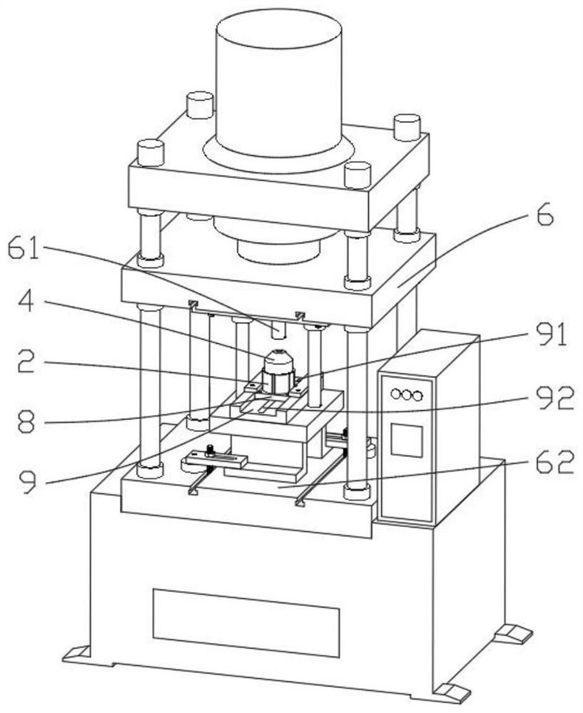
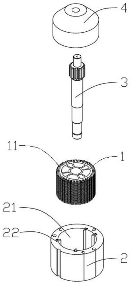
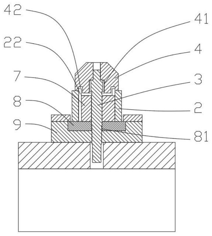
[0037] refer to Figure 1 to Figure 7 , a rotor core stacking mold, including a core punching positioning seat 2 for circumferential positioning of the stacked rotor core punching 1, a rotor shaft for axially compressing the rotor shaft 3 The pressing seat 4 and the iron core pressing seat 5 for axially compressing the rotor core punch 1, the rotor shaft pressing seat 4 and the iron core pressing seat 5 are both located on the core Above the punch positioning seat 2, the iron core punch positioning seat 2 performs ci...
PUM
 Abstract
Description
Claims
Application Information