Tool for machining oil injection ring and method for machining oil injection ring through tool

A technology of oil injection ring and tooling, which is applied in the direction of metal processing equipment, metal processing machine parts, manufacturing tools, etc. It can solve the problems of low processing efficiency and inability to guarantee the dimensional accuracy of processing parts, so as to improve product quality, speed up production progress, Effect of Optimizing Cutting Parameters

Active Publication Date: 2021-08-20
HARBIN TURBINE +1
View PDF11 Cites 0 Cited by
  • Summary
  • Abstract
  • Description
  • Claims
  • Application Information

AI Technical Summary

Problems solved by technology

[0004] The purpose of the present invention is to solve the problem that the existing processing method needs multiple clamping processing, the processing efficiency is low, and the dimensional accuracy of each processing part cannot be guaranteed

Method used


Image

  • Tool for machining oil injection ring and method for machining oil injection ring through tool
  • Tool for machining oil injection ring and method for machining oil injection ring through tool
  • Tool for machining oil injection ring and method for machining oil injection ring through tool

Examples


specific Embodiment approach 1

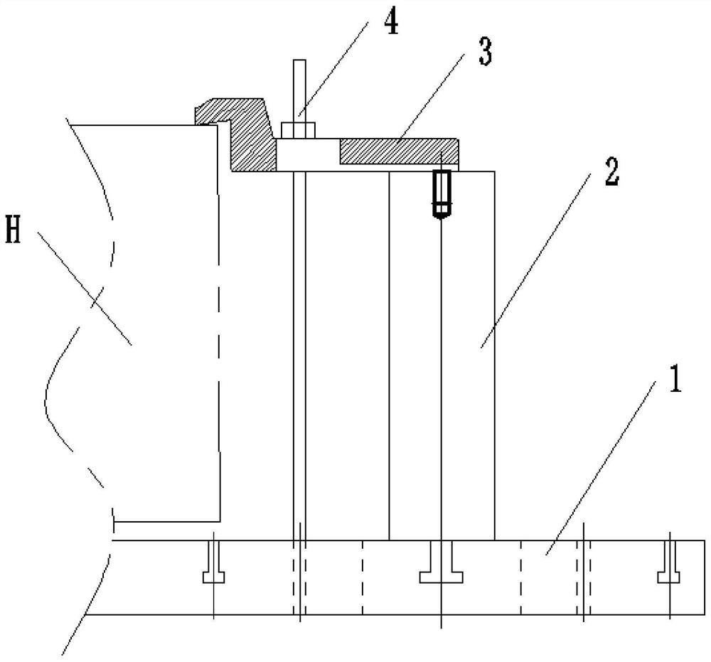
[0022] Specific implementation mode one: combine Figure 1 to Figure 5 Describe this embodiment, a tooling for a gas turbine fuel injection ring in this embodiment, which includes a base 1, a plurality of stepped support columns 2, a plurality of movable bending plates 3 and a plurality of connecting assemblies 4,

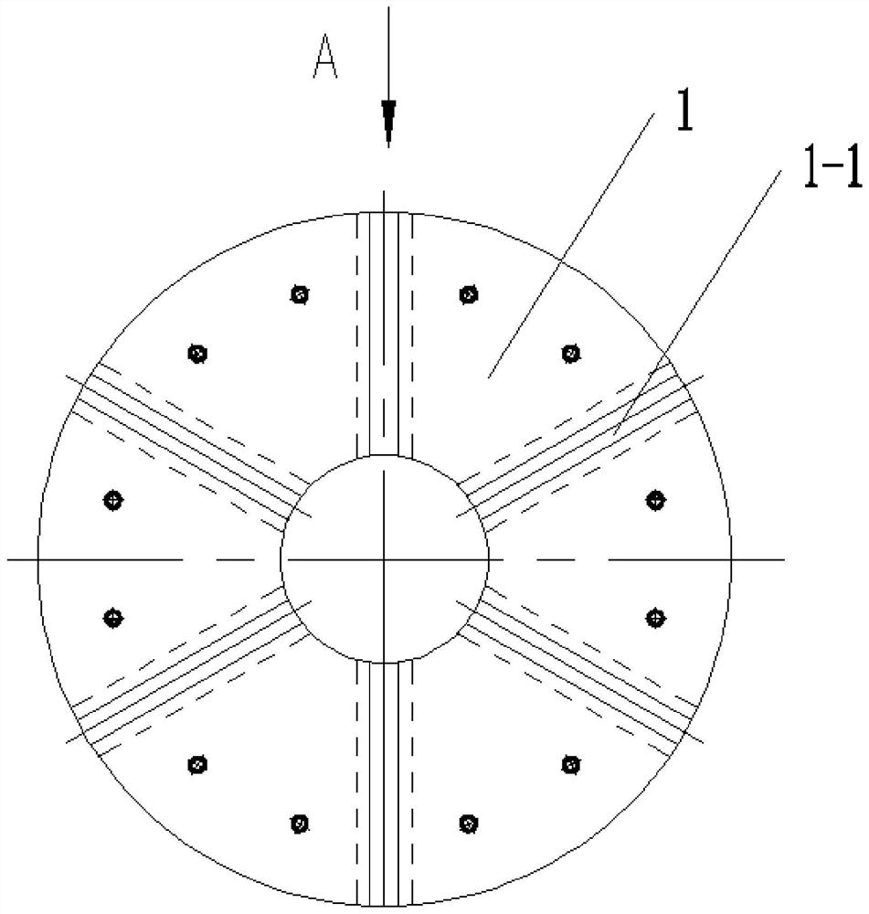
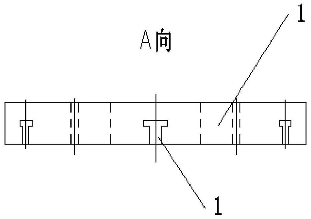
[0023] The base 1 is a disc-shaped seat, and a plurality of inverted T-shaped grooves 1-1 are provided in the form of a circular array on the base 1, and a stepped support column 2 is slidably installed in each inverted T-shaped groove 1-1. The oil ring H is coaxially installed on the base 1, and a plurality of movable bending plates 3 are press-fitted on the upper end surface of the oil injection ring H and the upper end surface of the stepped support column 2, and the movable bending plate 3 and the base 1 are connected by Component 4 is detachably connected.

specific Embodiment approach 2

[0024] Specific implementation mode two: combination figure 1 with Figure 4 This embodiment will be described. The number of inverted T-shaped grooves 1-1 in this embodiment is six. Such setting facilitates clamping according to the actual size of the fuel injection ring. In addition, the use of six inverted T-shaped grooves 1-1 can satisfy the symmetry and precision of clamping. Other components and connections are the same as those in the first embodiment.

specific Embodiment approach 3

[0025] Specific implementation mode three: combination figure 1 with Figure 5 To illustrate this embodiment, the mobile bending plate 3 of this embodiment includes a main clamping section 3-1 and an auxiliary clamping section 3-2, and the auxiliary clamping section 3-2 is fixedly installed on the left end of the main clamping section 3-1. And the clamping surface of the main clamping section 3-1 is lower than the clamping surface of the auxiliary clamping section 3-2. Such arrangement facilitates the firmness of the clamping. Other compositions and connections are the same as those in Embodiment 1

[0026] The function of the bottom plate with grooves in this embodiment: the base plays the role of a bond connecting the stepped support column with the workbench. The design of the dovetail groove of the base is mainly to fix the supporting column and the bolt with groove, and increase the stability of the supporting column and the bolt.

[0027] The function of tooling: thi...


PUM


Abstract

The invention discloses a tool for machining an oil injection ring and a method for machining the oil injection ring through the tool, and relates to a 1000 mm last-stage moving blade. The problems that according to an existing machining method, multiple times of clamping machining are needed, the machining efficiency is low, and the dimensional precision of all machined parts cannot be guaranteed are solved. A plurality of inverted-T-shaped grooves are formed in a base in an annular array mode, a step-shaped supporting column is installed in each inverted-T-shaped groove in a sliding mode, a plurality of movable bending and pressing plates are installed on the upper end face of an oil injection ring and the upper end faces of the step-shaped supporting columns in a pressing mode, and the movable bending and pressing plates and the base are detachably connected through connecting assemblies. The method comprises the following steps: 1, selecting proper equipment and clamping; 2, machining the oil injection ring H; 3, conducting clamping for the second time; and 4, carrying out finish machining on the size of the oil injection ring H. The method is used for machining the oil injection ring.

Description

technical field [0001] The invention relates to a tool and a method for processing an oil injection ring, in particular to a tool for processing an oil injection ring and a method for using the tool to process an oil injection ring. Background technique [0002] The fuel injection ring in the gas turbine unit has many parts to be processed, and the distribution is relatively scattered. For example, three 19mm wide bosses (0-0.3mm bosses on the back of the platform) are distributed in the inner hole; one 7mm wide boss, 5 5mm wide bosses, 3 ф4 oblique holes distributed in the outer circle; 3 ф2 holes, 3 ф0.8 holes on the upper end surface (front view); 1 6mm wide boss at the bottom (front view) The ф4 hole on the end face is connected with the ф2 and ф0.8 holes respectively. According to the traditional processing method, multiple clamping and processing are required. Not only the processing efficiency is low, but also the dimensional accuracy of each processing part cannot be...

Claims


Application Information

Patent Timeline
Patent Type & Authority Applications(China)
IPC IPC(8): B23Q3/06B23P15/00
CPCB23Q3/062B23P15/00
Inventor 杨凤吕思佳张隆张武成林彬彬陈国宏宗绍艳庞公臣鲁航
Owner HARBIN TURBINE
Why Eureka
Try Eureka