Supercharge Your Innovation With Domain-Expert AI Agents!

Production device and method of waterproof wire

A production device and production method technology, which is applied in the manufacturing of electrical components, circuits, cables/conductors, etc., and can solve problems such as gaps, potential safety hazards in use, and metal wire bonding of insulating layers.

Inactive Publication Date: 2021-08-20
深圳市汇昇科技发展有限公司
View PDF5 Cites 0 Cited by
  • Summary
  • Abstract
  • Description
  • Claims
  • Application Information

AI Technical Summary

Problems solved by technology

[0003] However, some cables are often multi-core metal wires. When these multi-core metal wires are combined, their cross-sectional profile is not a circle, but a "quincunx shape" with multiple circles tangent. If these metal wires are directly If the outer side is covered with an insulating layer, the insulating layer is not completely attached to the metal wire, but there is a gap
Therefore, in the actual use process, the water in the external environment is easy to enter between the insulating layer and the metal wire from both ends of the wire end, resulting in potential safety hazards in use.

Method used


Image

  • Production device and method of waterproof wire
  • Production device and method of waterproof wire
  • Production device and method of waterproof wire

Examples


Embodiment 1

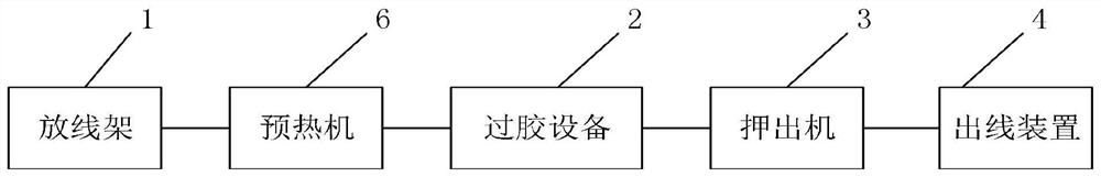
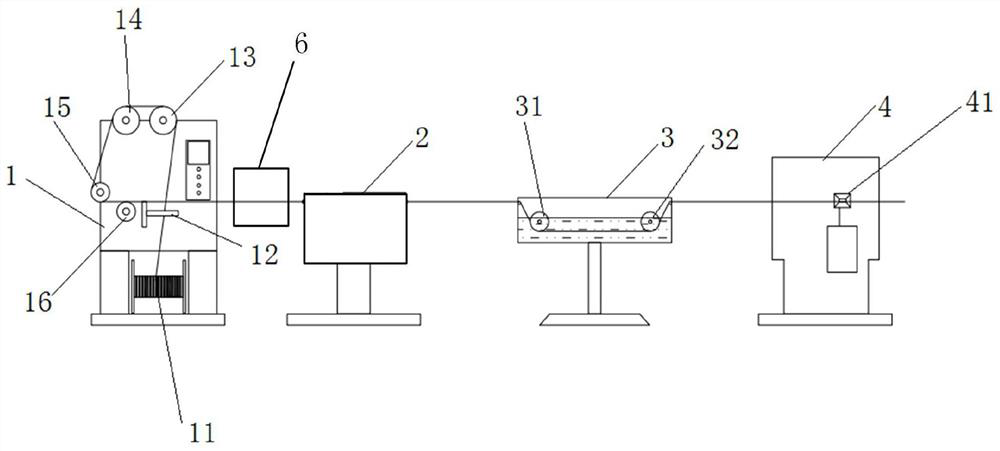
[0027] This embodiment proposes a production device for a waterproof line, combining Figure 1 to Figure 5 As shown, it includes a pay-off rack 1, an extruder 3 and an outlet device 4, and the pay-off rack 1, the extruder 3 and the outlet device 4 are connected in sequence, and it is characterized in that the pay-off rack 1 Glue-passing equipment 2 is also provided between the extruder 3, and the wire core 100 delivered by the pay-off frame 1 passes through the glue-passing equipment 2, the extruder 3 and the wire outlet device 4 in sequence, so that The glue passing device 2 is filled with hot melt adhesive 200 in a molten state, and the wire core 100 passes through the hot melt adhesive 200 .

[0028] In the production process of the above-mentioned device, the hot melt adhesive 200 with a preset temperature and in a molten state is firstly filled in the glue-passing equipment 2, and then the wire cores 100 delivered by the pay-off frame 1 are sequentially passed through the...

Embodiment 2

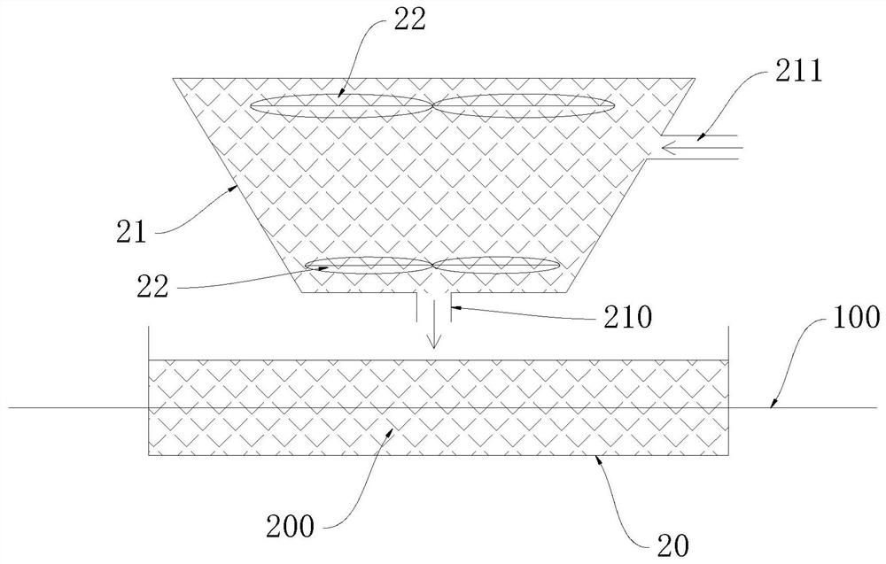
[0044] combine Figure 6 to Figure 8 As shown, this embodiment is a technical extension of Embodiment 1, which is used to perform secondary processing on the wire core coated with an insulating jacket, that is, after the metal shielding layer 103 is provided on the outer side of the insulating jacket, the insulating jacket 102 and the Hot-melt glue is also added between the cable jackets 104, and the process method adopted is close to that of the embodiment. Because the hot-melt glue is set on the outside of the insulating jacket 102 in this process flow, there is no need to add a preheating process, and only the insulation The jacket 102 and the metal shielding layer 103 are sequentially processed through the gluing equipment 2, the extruder 3 and the outlet device 4, so that the insulating jacket 102 and the metal shielding layer 103 are coated with a hot melt adhesive layer, and then The extruder 3 is used to process and form the insulating jacket 102 to obtain a cable with...


PUM


Abstract

The invention discloses a production device of a waterproof wire. The production device comprises a pay-off rack, an extruder and a wire outlet device, the pay-off rack, the extruder and the wire outlet device are connected in sequence, and a gluing device is further arranged between the pay-off rack and the extruder. A wire core conveyed by the pay-off rack sequentially passes through the gluing device, the extruder and the wire outlet device, the gluing device is filled with a hot melt adhesive in a molten state, and the wire core penetrates through the hot melt adhesive. According to the waterproof production device of the wire, the waterproof problem between the outer sleeve and the wire core or a semi-finished product is solved, the waterproof problem of the whole industry is technically broken through, automatic production operation can be achieved, and the productivity can be effectively improved. The hot melt adhesive liquid is more stably attached to the wire core or the semi-finished product under precise temperature control, and then the hot melt adhesive liquid is more tightly attached to the insulating jacket, so that the complete waterproof effect is achieved.

Description

Technical field: [0001] The invention relates to the technical field of cable processing and production, in particular to a production device and method for a waterproof thread. Background technique: [0002] The existing cable processing device is used for power lines, power cables, coaxial cables, communication cables, transmission cables, BV civilian lines, electronic lines, computer lines, construction lines, data communication cables, radio frequency lines, HDMI data lines, When processing and producing various types of high-temperature silicone cables, Teflon cables, coaxial cables, etc., the general process is: first, the metal wires come out of the pay-off frame and pass through the head of the main machine, and at the same time, the suction machine sucks in the rubber for heating-then the main machine heats the metal The wire is covered with glue-and then pulled by the drawing machine-finally to the wire take-up machine to take up the wire and coil it. [0003] How...

Claims


Application Information

Patent Timeline
IPC IPC(8): H01B13/00H01B13/24
CPCH01B13/0036H01B13/24
Inventor 龙美林
Owner 深圳市汇昇科技发展有限公司
Features
  • R&D
  • Intellectual Property
  • Life Sciences
  • Materials
  • Tech Scout
  • Unparalleled Data Quality
  • Higher Quality Content
  • 60% Fewer Hallucinations
Learn More