
Reed type low-board-spacing elastic radio frequency connector

A radio frequency connector and reed type technology, which is applied in the direction of connection, two-part connection device, parts of the connection device, etc., can solve the application scenarios that cannot meet the low board spacing, the axial length of the radio frequency connector is large, and the connector Problems such as large axial dimension are beneficial to miniaturization, strong structural stability, and reduced difficulty in forming and assembling

Active Publication Date: 2021-08-20
CHINA AVIATION OPTICAL-ELECTRICAL TECH CO LTD
View PDF15 Cites 0 Cited by
  • Summary
  • Abstract
  • Description
  • Claims
  • Application Information

AI Technical Summary

Problems solved by technology

The traditional RF connector includes an outer conductor and an inner conductor coaxially installed in the outer conductor. The inner conductor adopts a pin, and the pin can be axially floating. A jack that matches the pin is provided on the printed board. After quasi-mating, the vertical connection between the boards is realized. The floating pin generally uses elastic elements to realize the axial floating function, resulting in a large axial dimension of the connector, and the board spacing of the printed board increases accordingly.
Therefore, the axial length of this type of RF connector, which cooperates with pins and jacks to realize vertical interconnection between boards, is relatively large, which cannot meet the application scenarios of low board spacing

Method used


Image

  • Reed type low-board-spacing elastic radio frequency connector
  • Reed type low-board-spacing elastic radio frequency connector
  • Reed type low-board-spacing elastic radio frequency connector

Examples


Embodiment Construction

[0033] The technical solutions of the present invention will be further described in detail below in conjunction with the accompanying drawings and preferred embodiments.

[0034] In describing the present invention, it is to be understood that the terms "center", "upper", "lower", "front", "rear", "left", "right", "vertical", "horizontal", The orientations or positional relationships indicated by "top", "bottom", "inner", "outer", etc. are based on the orientations or positional relationships shown in the drawings, and are only for the convenience of describing the present invention and simplifying the description, rather than indicating or implying References to devices or elements must have a particular orientation, be constructed, and operate in a particular orientation and therefore should not be construed as limiting the invention. In addition, terms indicating the quantity of corresponding technical features such as "first" and "second" are only used for description pur...


PUM


Abstract

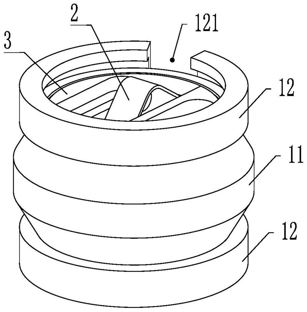
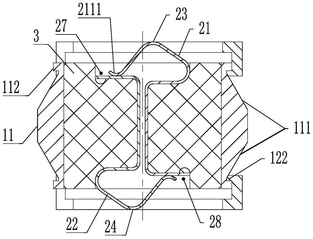
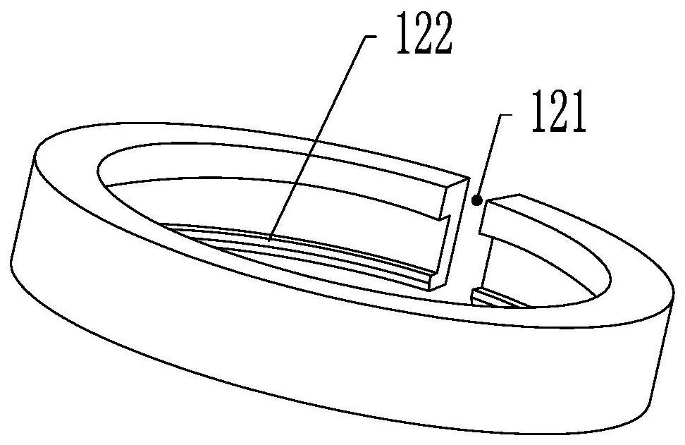
The invention relates to a reed type low-board-spacing elastic radio frequency connector which comprises an outer conductor, an inner conductor and an insulator. The outer conductor comprises a first outer shell, the upper end and the lower end of the first outer shell are respectively provided with a second outer shell, the second outer shells can elastically float along the axial direction relative to the first outer shell, and the insulator is arranged in the first outer shell; the inner conductor comprises a first reed and a second reed which are arranged in a central symmetry mode, the first reed comprises a first elastic piece part and a first installation part which are connected, and the second reed comprises a second elastic piece part and a second installation part which are connected; the first elastic piece part is provided with an upper contact point which is in elastic contact with the upper printed board and a first side contact point which is in elastic contact with the second installation part; and the second elastic piece part is provided with a lower contact point which is in elastic contact with the lower printed board and a second side contact point which is in elastic contact with the first installation part. The space between the printed boards can be reduced, transmission of high-speed radio-frequency signals is facilitated, and the forming difficulty and the assembling difficulty of the inner conductor and the insulator are reduced.

Description

technical field [0001] The invention belongs to the technical field of radio frequency connectors, in particular to a reed type elastic radio frequency connector with low board spacing. Background technique [0002] Inter-board RF connectors are used between two printed boards that need to be interconnected to realize RF signal transmission between printed boards. The traditional RF connector includes an outer conductor and an inner conductor coaxially installed in the outer conductor. The inner conductor adopts a pin, and the pin can be axially floating. A jack that matches the pin is provided on the printed board. After quasi-mating, the vertical connection between the boards is realized. The floating pin generally uses elastic elements to realize the axial floating function, resulting in a larger axial dimension of the connector, and an increase in the board spacing of the printed board. Therefore, the axial length of this kind of radio frequency connector that cooperate...

Claims


Application Information

Patent Timeline
IPC IPC(8): H01R13/24H01R13/502H01R13/02H01R13/631H01R24/40
CPCH01R13/24H01R13/502H01R13/02H01R13/6315H01R24/40
Inventor 薛寒冰王学习
Owner CHINA AVIATION OPTICAL-ELECTRICAL TECH CO LTD
Learn More