
Touch system

It is a main body and transparent technology, which is applied in the direction of instruments, electrical digital data processing, and input/output process of data processing. Vibration, low precision requirements, not easy to aging effect

Active Publication Date: 2016-10-12
HUZHOU ZAAG ELECTRIC TECH
View PDF7 Cites 0 Cited by
  • Summary
  • Abstract
  • Description
  • Claims
  • Application Information

AI Technical Summary

Problems solved by technology

In this technical solution, it is necessary to ensure that the relative positions of the light source, the light guide assembly, the light receiver, and the touch panel are fixed. Any vibration or position change of any one of the components will cause a change in the emission angle of the light source, thereby affecting the light source through total reflection. The light intensity propagating to the optical receiver is very likely to cause misjudgment of touch and directly affect the touch accuracy of the touch screen
Especially in the link of the light guide component, some slight deviations in the angle of the light acting surface are likely to be amplified, thereby destroying the total reflection of light in the touch screen substrate

Method used


Image

  • Touch system
  • Touch system
  • Touch system

Examples


Embodiment Construction

[0025] Embodiments of the present invention will be described in detail below with reference to the accompanying drawings.

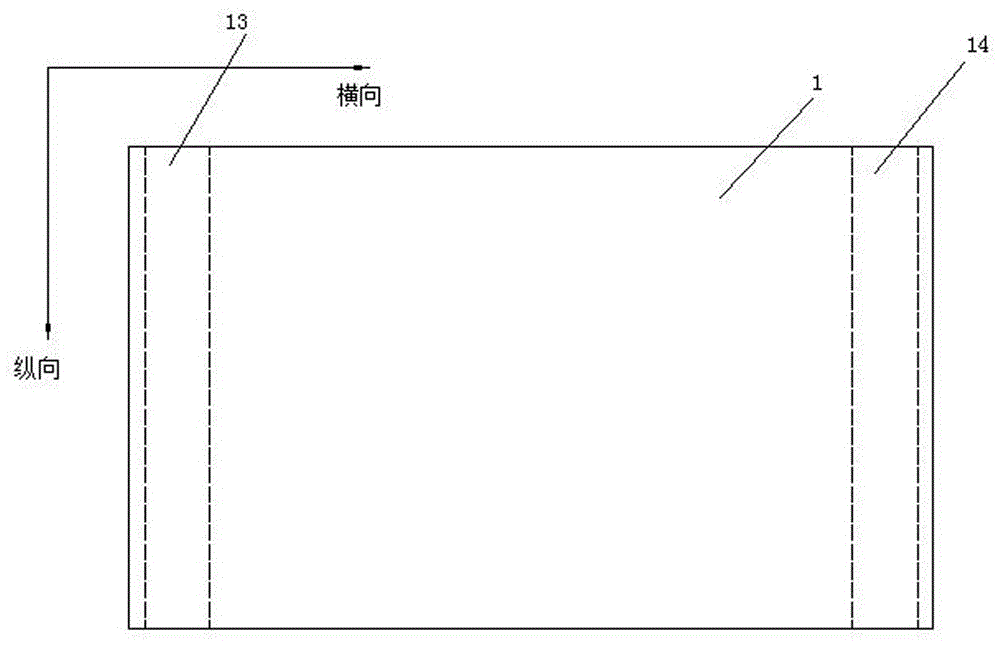
[0026] Such as figure 1 , 2 , a touch system, including a glass panel 1, an infrared emitting tube 2, and an infrared receiving tube 3. The glass panel 1 comprises a top surface 11 and a bottom surface 12 parallel to each other, and the inside of the glass panel 1 is provided with a first light reflection strip 13 and a second light reflection strip 14 extending longitudinally along the glass panel 1 at both ends in the transverse direction. . A plurality of infrared emitting tubes 2 are fixedly installed below the first light reflection band 13 along the longitudinal direction of the glass panel 1, and a plurality of infrared receiving tubes 3 corresponding to the infrared emitting tubes 2 are fixedly installed on the second light reflecting band along the longitudinal direction of the glass panel 1. 14 below.

[0027] The first light reflective str...


PUM

PropertyMeasurementUnit
Widthaaaaaaaaaa
Diameteraaaaaaaaaa

Abstract

The invention relates to the technical field of touch screens, in particular to a touch system. The touch system comprises a transparent main body with a top face and a bottom face, one end of the transparent main body is provided with a light emitting tube, and the other end of the transparent main body is provided with a light receiving tube; the light emitting tube is fixedly connected with the transparent main body, and the light receiving tube is fixedly connected with the transparent main body. The touch system is characterized in that a first light reflection band and a second light reflection band which extend in the longitudinal direction of the transparent main body are transversely arranged in the transparent main body; the first light reflection band is arranged over the light emitting tube, and the second light reflection band is arranged over the light receiving tube; the first light reflection band comprises a first specular reflection part and a first diffuse reflection part, and the first specular reflection part enables light emitted by the light emitting tube to achieve total internal reflection in the transparent main body; the second light reflection band comprises a second specular reflection part and a second diffuse reflection part, and the second specular reflection part enables the light achieving total internal reflection in the transparent main body to leave from the transparent main body to be received by the light receiving tube.

Description

technical field [0001] The invention relates to the technical field of touch screens, in particular to a touch system. Background technique [0002] The application number is CN 104679346A, and the invention patent application published on June 3, 2015 discloses a multi-point touch screen based on suppressed internal reflection technology. It includes a touch screen substrate forming total internal reflection, a light source close to the non-touch surface of the touch screen substrate, a light guide assembly that guides the light source into the touch screen substrate to form total internal reflection, and a light receiver that receives light that has undergone total internal reflection. Place the parts on the non-touch surface of the touch screen substrate, change the emission angle of the light source through the light guide assembly (ensure that the incident angle of light on the touch surface of the touch substrate is greater than the critical angle between the touch sub...

Claims


Application Information

Patent Timeline
IPC IPC(8): G06F3/042
CPCG06F3/042
Inventor 李金鹏齐洋周建王迪
Owner HUZHOU ZAAG ELECTRIC TECH
Learn More