A hydraulic wire terminal crimping machine
A terminal crimping machine and electric wire technology, applied in the direction of connection, circuit, electrical components, etc., can solve the problems of ground wire fatigue, uneven stress on the ground wire, broken strands, etc.
- Summary
- Abstract
- Description
- Claims
- Application Information
AI Technical Summary
Problems solved by technology
Method used
Image
Examples
Embodiment 1
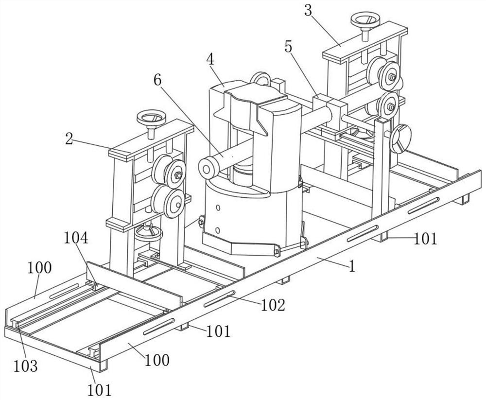
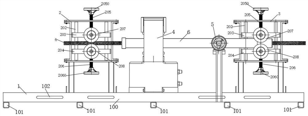
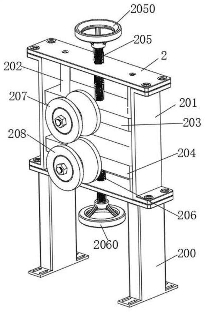
[0072] The embodiment of the present invention provides a hydraulic wire terminal crimping machine, such as Figure 1-11As shown, a bracket assembly 1 is included, a first clamping assembly 2 and a second clamping assembly 3 are slidably connected to the bracket assembly 1, and between the first clamping assembly 2 and the second clamping assembly 3 A crimping equipment assembly 4 is provided, and the crimping equipment assembly 4 is slidably connected with the bracket assembly 1, and the sliding direction is aligned with the sliding direction of the first clamping assembly 2 and the second clamping assembly 3 On a straight line, a secondary clamping component 5 is provided between the crimping equipment component 4 and the second clamping component 3 , and the secondary clamping component 5 is detachably connected to the bracket component 1 .
[0073] The working principle and beneficial effects of the above technical solution are as follows: clamp the two electric wires 6 to...
Embodiment 2
[0075] On the basis of above-mentioned embodiment 1, as Figure 1-8 As shown, the bracket assembly 1 includes two symmetrically arranged angle steels 100, the bottoms of the two angle steels 100 are fixedly connected with several square steel connecting rods 101, the intervals between the several square steel connecting rods 101 are the same, and the side walls of the two angle steels 100 There are several connecting grooves 102 on each of them, and the secondary clamping assembly 5 is detachably connected in the connecting grooves 102;
[0076] The two angle steels 100 are provided with I-shaped slide rails 103, the first clamping assembly 2 and the second clamping assembly 3 are slidably connected to the I-shaped slide rails 103, and the first clamping assembly The component 2 and the second clamping component 3 are provided with a connecting slider 104 that is slidably matched with the I-shaped slide rail 103, and the first clamping component 2 and the second clamping compo...
Embodiment 3
[0102]On the basis of Embodiment 1 or 2, a straightness detection and adjustment mechanism 7 is detachably connected to the bracket assembly 1, and the straightness detection and adjustment mechanism 7 includes a detection base 700, and the bottom of the detection base 700 is fixedly connected with two Symmetrically arranged detection mechanism adjustment slider 7000, the detection mechanism adjustment slider 7000 is provided with an adjustment slider driver, and the adjustment slider driver is used to drive the detection mechanism adjustment slider 7000 along the bracket assembly 1 sliding, the sliding direction is the same as the axial direction of the wire 6, the detection base 700 is fixedly connected with a mounting plate 7001, and the mounting plate 7001 is fixedly connected with a first mounting plate 7002 and a second mounting plate 7003, the first An adjustment screw 7004 is rotatably connected between the installation plate 7002 and the second installation plate 7003,...
PUM
 Abstract
Description
Claims
Application Information
 - R&D
- Intellectual Property
- Life Sciences
- Materials
- Tech Scout
- Unparalleled Data Quality
- Higher Quality Content
- 60% Fewer Hallucinations
Browse by: Latest US Patents, China's latest patents, Technical Efficacy Thesaurus, Application Domain, Technology Topic, Popular Technical Reports.
© 2025 PatSnap. All rights reserved.Legal|Privacy policy|Modern Slavery Act Transparency Statement|Sitemap|About US| Contact US: help@patsnap.com


