
Reverse electromotive force active discharge protection circuit and active arc extinguishing method

A reverse electromotive force and protection circuit technology, applied in emergency protection circuit devices, emergency protection circuit devices for limiting overcurrent/overvoltage, circuit devices, etc., can solve problems such as slow speed, circuit failure, and contact burning , to achieve the effect of saving installation space, no residual pressure problem, and meeting actual needs

Pending Publication Date: 2021-08-20
浙江南晶电气有限公司
View PDF0 Cites 3 Cited by
  • Summary
  • Abstract
  • Description
  • Claims
  • Application Information

AI Technical Summary

Problems solved by technology

[0002] When the switch or relay shuts off the power supply of inductive devices such as motors and electromagnets, the reverse electromotive force often causes arcing on the contacts, causing the contacts to burn and eventually causing circuit failures
[0003] The existing solution is to connect components such as "resistance-capacity absorption circuit", "thermistor", "transient suppression regulator tube" and other components in parallel on both ends of the switch or relay contacts to absorb the reverse electromotive force, but the protection of these passive components The effect is limited, or the residual pressure is too high, or the absorption is limited, or the speed is not fast, etc., each has its own disadvantages

Method used


Image

  • Reverse electromotive force active discharge protection circuit and active arc extinguishing method
  • Reverse electromotive force active discharge protection circuit and active arc extinguishing method
  • Reverse electromotive force active discharge protection circuit and active arc extinguishing method

Examples


Embodiment Construction

[0027] Below will combine the embodiment of the present invention Figure 1 to Figure 4 , clearly and completely describe the technical solutions in the embodiments of the present invention, obviously, the described embodiments are only some of the embodiments of the present invention, not all of them. Based on the embodiments of the present invention, all other embodiments obtained by persons of ordinary skill in the art without creative efforts fall within the protection scope of the present invention.

[0028] In order to make the objectives, technical solutions and advantages of the present invention clearer, the technical solutions in the embodiments of the present invention will be described in more detail below in conjunction with the drawings in the embodiments of the present invention.

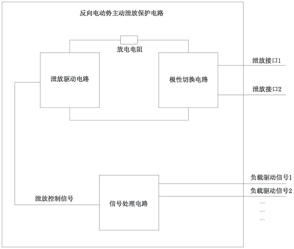
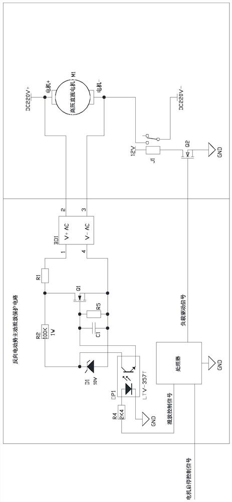
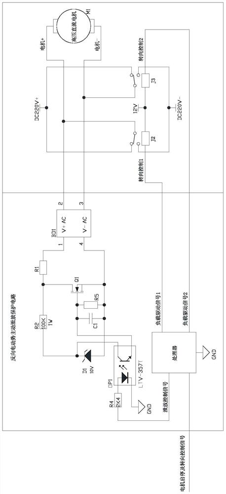
[0029] Such as Figure 1 to Figure 4 As shown, a reverse electromotive force active discharge protection circuit disclosed in this embodiment includes a signal processing circuit, a ...


PUM


Abstract

The invention relates to the field of direct current system protection, in particular to a reverse electromotive force active discharge protection circuit which comprises a signal processing circuit, a discharge driving circuit, a discharge resistor and a polarity switching circuit, wherein one end of the discharge resistor is electrically connected with the polarity switching circuit, the other end is electrically connected with the discharge driving circuit, the polarity switching circuit and the signal processing circuit are both electrically connected with the discharge driving circuit, the polarity switching circuit is provided with two discharge interfaces used for being connected in parallel with a direct-current load, and the signal processing circuit outputs a load driving signal used for controlling the direct-current load and a discharge control signal used for controlling the discharge driving circuit. The reverse electromotive force active discharge protection circuit provided by the invention can actively extinguish arc, and can solve the problem that a switch or a relay contact is damaged by reverse electromotive force generated by an inductive device. The invention further provides an active arc extinguishing method based on the reverse electromotive force active discharge protection circuit. The method deals with reverse electromotive forces that are harmful to the circuit in an active and advanced intervention manner.

Description

technical field [0001] The invention relates to the technical field of DC system protection, in particular to a back electromotive force active discharge protection circuit and an active arc extinguishing method. Background technique [0002] When the switch or relay shuts off the power supply of inductive devices such as motors and electromagnets, the reverse electromotive force often causes arcing on the contacts, causing the contacts to burn and eventually causing circuit failures. [0003] The existing solution is to connect components such as "resistance-capacity absorption circuit", "thermistor", "transient suppression regulator tube" and other components in parallel on both ends of the switch or relay contacts to absorb the reverse electromotive force, but the protection of these passive components The effect is limited, or the residual pressure is too high, or the absorption is limited, or the speed is not fast, etc., each has its own disadvantages. For above-mentio...

Claims


Application Information

Patent Timeline
Patent Type & Authority Applications(China)
IPC IPC(8): H02H9/04H02H9/08H02H7/09
CPCH02H7/09H02H9/047H02H9/08
Inventor 赵佩云朱忠芳朱蝶郑瑞象
Owner 浙江南晶电气有限公司
Learn More