

Circuit board and motor
A circuit board and motor technology, applied in printed circuits, printed circuits, printed circuit manufacturing, etc., can solve the problems of long inspection time, equipment investment, and inability to confirm poor welding, and achieve the effect of simple inspection and simple poor welding
- Summary
- Abstract
- Description
- Claims
- Application Information
AI Technical Summary
Problems solved by technology
Method used
Image

Examples
no. 1 approach
[0033]
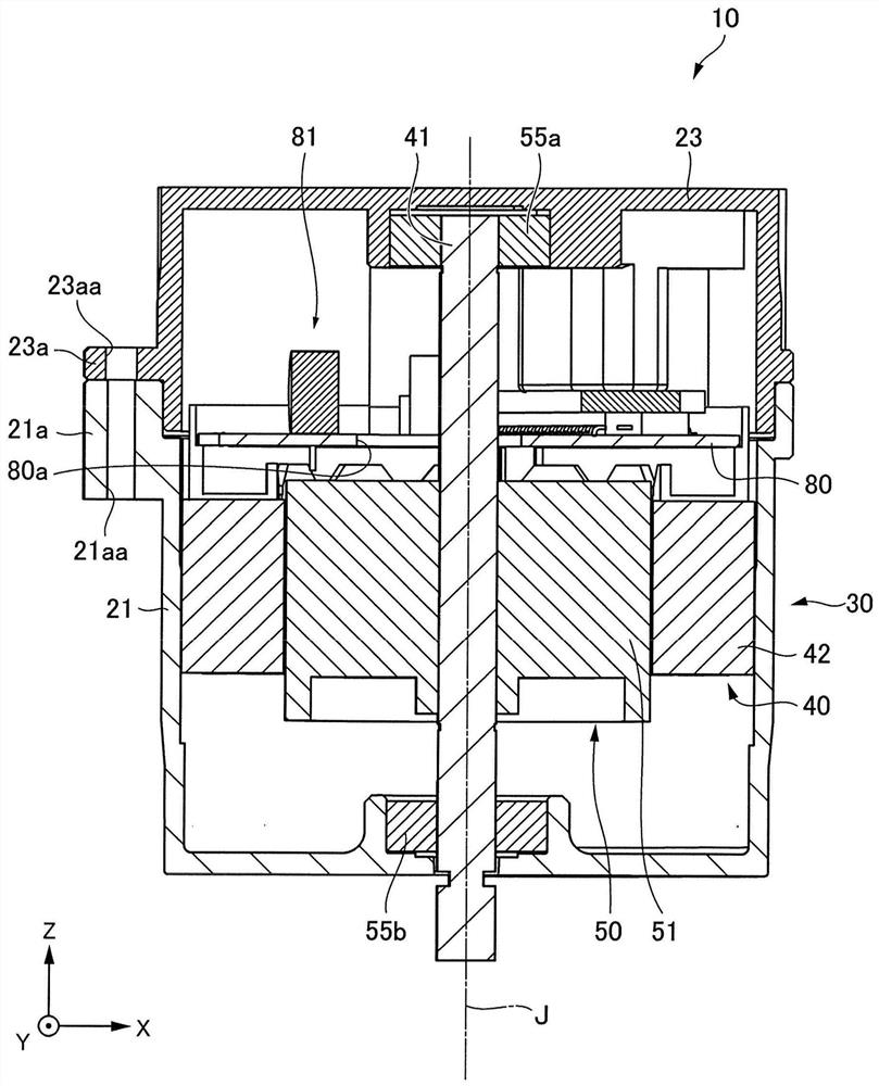
[0034] figure 1 It is a sectional view of a motor driving device and a motor shown with the Y axis and perpendicular to the first embodiment of the present invention through the center axis of the cutting plane J.
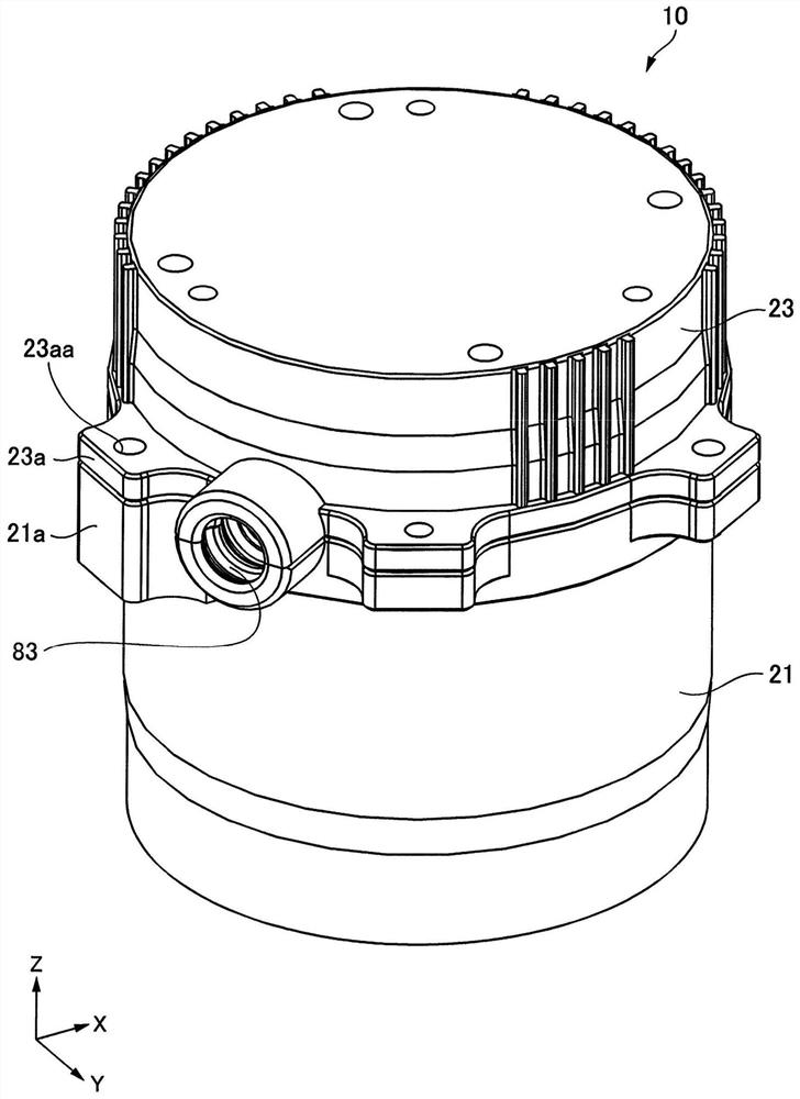
[0035] figure 2 Yes figure 1 10 is a perspective view of the motor.
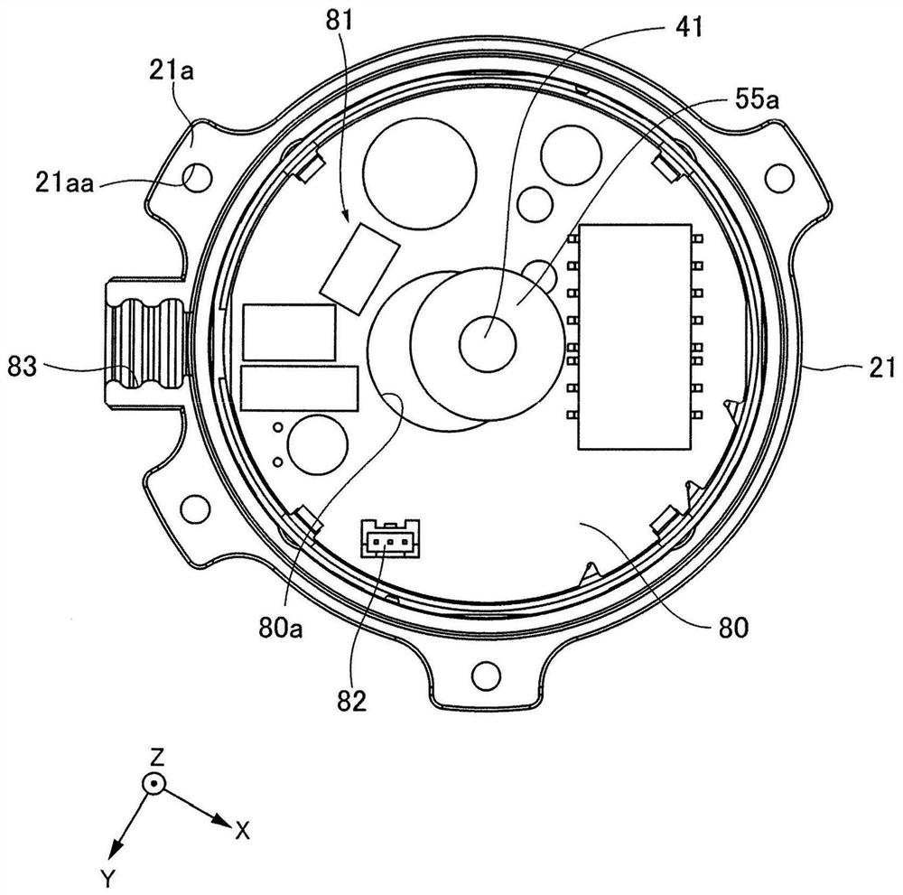
[0036] In the present embodiment, the motor 10 is a brushless DC motor. Na Mada receiving portion 10 having a motor 30 and a motor casing 80 of the circuit board 21 and 23, wherein the motor portion 30 having a rotor 50 and stator 40, the circuit board 80 is mounted a drive circuit 81 as a drive motor 30. The rotor 50 has a motor shaft disposed along the central axis J extending in the axial direction 41. The stator 40 and the rotor 50 via a gap in the radial direction and opposite. 21 and 23 to the motor housing axially toward the other side arranged in this order from one axial side of the circuit board 80 and the rotor 50 is accommodated embodiment.
[0037] The stator 40 has a stator ...
Embodiment 1
[0044] The circuit board 80 of the first embodiment is, for example, a driving circuit 81 equipped with a driving circuit of the motor portion 30, and is housed in a circuit board of the motor shells 21 and 23.
[0045]
[0046] Figure 4 It is a top plan view showing a substrate constituting the circuit board of Embodiment 1 of the present invention. Figure 4 The state before being mounted on the substrate is shown. Figure 5 It is a top plan view showing the structure of the circuit board of Embodiment 1 of the present invention. Figure 5 A state after mounting the electronic component to the substrate. Image 6 Be an observation Figure 5 The surface view of the surface of the electronic component is opposed to the surface of the substrate.
[0047] The substrate 84 is mounted with an electronic component 92. When the electronic component 92 is mounted on the substrate 84, the paste solder is used in a water welding manner. The substrate 84 is a rigid substrate. The substrate 84 ...
Embodiment 2
[0065] The circuit board 180 of the second embodiment is, for example, a driving circuit 81 or the like having a driving of the motor portion 30, and is housed in a circuit board of the motor shells 21 and 23.
[0066]
[0067] Figure 9 It is a plan view showing a substrate constituting the circuit board of the second embodiment of the present invention. Figure 9 The state before being mounted on the substrate is shown. Figure 10 It is a plan view showing the structure of a circuit board of Embodiment 2 of the present invention. Figure 10 A state after mounting the electronic component to the substrate. Figure 11 Be an observation Figure 10 The surface view of the surface of the electronic component is opposed to the surface of the substrate. Figure 12 Be an observation Figure 10 Side view of the surface of the electronic component with the substrate vertical.
[0068]The substrate 184 is equipped with an electronic component 192. When the electronic component 192 is mounted on ...
PUM
 Abstract
Description
Claims
Application Information