Eureka AIR delivers breakthrough ideas for toughest innovation challenges, trusted by R&D personnel around the world.

Hemostasis compressor for department of cardiology

A compression device and cardiology technology, applied in medical science, suction equipment, surgery, etc., can solve the pain of patients tearing and other problems

Pending Publication Date: 2021-08-24
王媛媛
View PDF5 Cites 0 Cited by
  • Summary
  • Abstract
  • Description
  • Claims
  • Application Information

AI Technical Summary

Problems solved by technology

[0004] In view of the deficiencies in the prior art, the purpose of the present invention is to provide a hemostatic compressor for cardiology to solve the problem in the prior art that the hemostatic compressor needs to be in contact with the patient's skin when the hemostatic compressor is used to stop bleeding from the patient's wound. For hemostasis, during the pressing process, the wound will overflow a lot of blood, and after half an hour of hemostasis, in the process of separating the compressor and the skin, due to blood coagulation, the patient may have tearing pain when separating Sensational defects

Method used


Image

  • Hemostasis compressor for department of cardiology
  • Hemostasis compressor for department of cardiology
  • Hemostasis compressor for department of cardiology

Examples


no. 1 example

[0031] Such as Figure 1-Figure 4 As shown, the present invention provides a technical scheme of a hemostatic compressor in the Department of Cardiology:

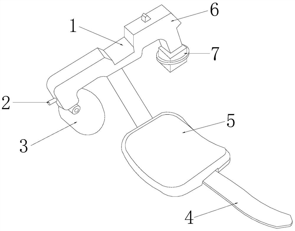
[0032] Such as Figure 1-Figure 2 As shown, a hemostatic compressor for cardiology, its structure includes a main body 1, an activation bar 2, a fixing plate 3, a fixing belt 4, a comfort pad 5, a pressure regulator 6, and a compression device 7, and the activation bar 2 is arranged on the main body 1 on the left side surface, the fixing plate 3 is installed on the left lower surface of the main body 1, one end of the fixing belt 4 is connected to the lower surface of the middle part of the main body 1, and the other end is exposed to the air through the comfort pad 5, the pressure The regulator 6 is located on the right side of the main body 1 and is an integrated structure. The compression device 7 is installed on the lower surface of the pressure regulator 6. The compression device 7 includes a downward pressure structu...

no. 2 example

[0040] Such as Figure 2-Figure 7 As shown, the present invention provides a technical scheme of a hemostatic compressor in the Department of Cardiology:

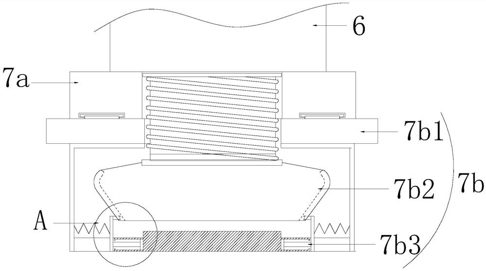
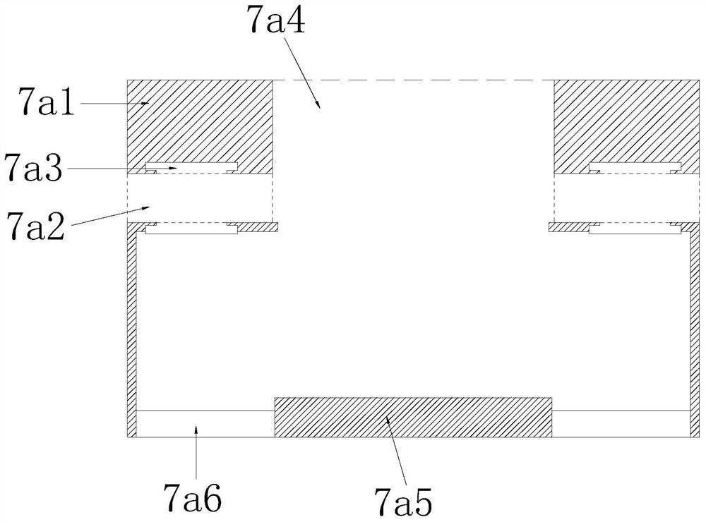
[0041] Such as figure 2As shown, a hemostatic compressor for cardiology, its structure includes that the drainage mechanism 7b includes an adjustment piece 7b1, a pusher piece 7b2, and a suction piece 7b3, the adjustment piece 7b1 passes through the collar frame 7a2, and the upper and lower parts are respectively Cooperate with the slide rail 7a3, the number of the suction piece 7b3 and the overflow bar 7a6 are consistent and matched, and the upper part of the suction piece 7b3 is connected with the push piece 7b2, which is beneficial to realize self-adjustment, and the compression The blood produced does the absorption.

[0042] like Figure 5 As shown, the adjustment member 7b1 includes an adjustment ring 7b11 and a movable track 7b12. The adjustment ring 7b11 passes through the collar frame 7a2 and is connected throu...


PUM


Abstract

The invention discloses a hemostasis compressor for the department of cardiology. The hemostasis compressor structurally comprises a main body, a starting strip, a fixing plate, a fixing belt, a comfortable pad, a pressure regulator and a compression device. The hemostasis compressor has the beneficial effects that overflow strips arranged on the downward pressing structure are matched with the pressing plate, so that overflowing blood can be spatially and orderly diffused in the pressing process, and the situation that the overflowing blood is pressed by the fixing frame, and after the overflowing blood is separated from the skin of a patient, tearing pain is caused due to blood coagulation, through the arranged drainage mechanism, blood overflowing from a wound can be effectively absorbed and treated after a medical worker conducts hemostasis compression on a patient, and the situation that the blood is coagulated on the skin of the patient after hemostasis for half an hour is avoided.

Description

technical field [0001] The invention relates to the field of medical equipment, more precisely, it is a hemostatic compressor in the department of cardiology. Background technique [0002] After the cardiology operation is completed, in order to avoid bleeding from the patient's wound, it is necessary to cooperate with a hemostatic compressor to safely stop bleeding from the patient's wound. [0003] When using a hemostatic compressor to stop bleeding from a patient's wound, since it is necessary to cooperate with the compressor to contact the patient's skin for hemostasis, during the pressing process, the wound will overflow a lot of blood, and after half an hour of hemostasis, the In the process of separating the compressor from the skin, due to blood coagulation, it is easy to cause the patient to feel tearing pain during separation. Contents of the invention [0004] In view of the deficiencies in the prior art, the purpose of the present invention is to provide a hem...

Claims


Application Information

Patent Timeline
Patent Type & Authority Applications(China)
IPC IPC(8): A61B17/12A61M1/00
CPCA61B17/12A61B2017/12004
Inventor 王媛媛
Owner 王媛媛
Why Eureka
Eureka Blog
Learn More