Soil pollution treatment device

A soil pollution and soil remediation technology, which is applied in the field of soil pollution control, can solve problems such as difficulty in spraying, easy to be evaporated gradually, and uneven mixing of soil remediation fluid, so as to improve the mixing effect, improve the mixing efficiency, and improve the efficiency of soil remediation. Effect

Inactive Publication Date: 2021-08-24
李伟
View PDF0 Cites 15 Cited by
  • Summary
  • Abstract
  • Description
  • Claims
  • Application Information

AI Technical Summary

Problems solved by technology

[0003] Existing soil pollution control devices mainly spray soil remediation liquid on the soil in the land. The soil remediation liquid can only be sprayed to the surface of the soil, and it is easy to be gradually evaporated. At the same time, it is difficult to spray into the deeper soil, and the soil remediation liquid is mixed Insufficient uniformity, leading to poor soil pollution control effect

Method used


Image

  • Soil pollution treatment device
  • Soil pollution treatment device
  • Soil pollution treatment device

Examples


Embodiment 1

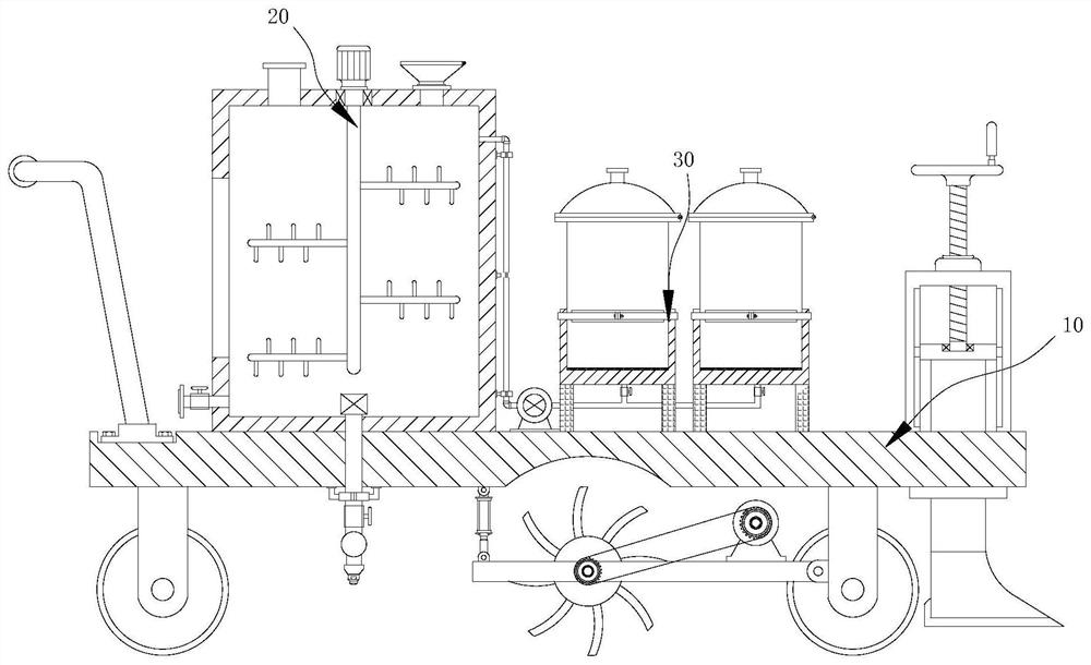
[0033] see Figure 1-5 , the present invention provides a technical solution: a soil pollution control device, including a soil turning mechanism 10 and a mixing and spraying mechanism 20 .

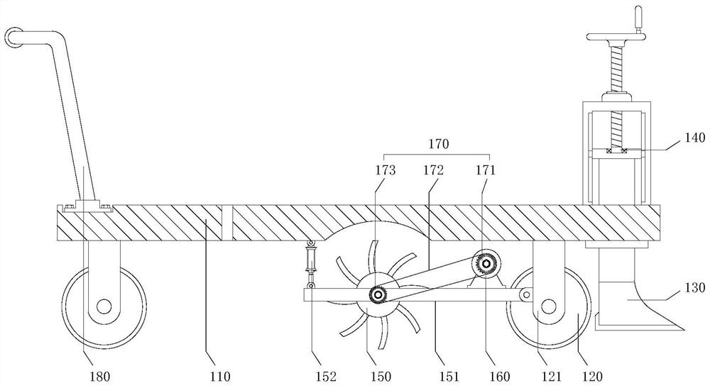
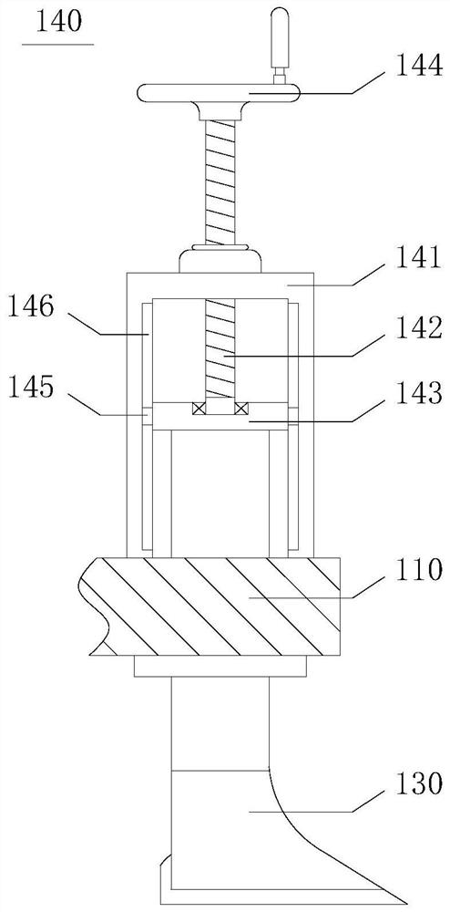
[0034] see figure 2 The soil-turning mechanism 10 includes a base 110, a height adjustment member 140, a crushing roller 150, and a first motor 160. The four corners of the bottom of the base 110 are equipped with rollers 120 through support legs 121, and the convenient movement of the soil-turning mechanism 10 is realized by using the rollers 120. The height adjustment member 140 is fixedly connected to one end of the top of the base 110, and several sets of plowshares 130 are uniformly arranged on the bottom of the height adjustment member 140, and the height of the plowshares 130 is synchronously adjusted through the height adjustment member 140 to control the turning depth of the soil, crush the soil The roller 150 is rotatably connected to the support leg 121 through the swing arm ...

Embodiment 2

[0040] see Figure 1-6 , the present invention provides a technical solution: a soil pollution control device, including a soil turning mechanism 10 and a mixing and spraying mechanism 20 .

[0041] see figure 2 The soil-turning mechanism 10 includes a base 110, a height adjustment member 140, a crushing roller 150, and a first motor 160. The four corners of the bottom of the base 110 are equipped with rollers 120 through support legs 121, and the convenient movement of the soil-turning mechanism 10 is realized by using the rollers 120. The height adjustment member 140 is fixedly connected to one end of the top of the base 110, and several sets of plowshares 130 are uniformly arranged on the bottom of the height adjustment member 140, and the height of the plowshares 130 is synchronously adjusted through the height adjustment member 140 to control the turning depth of the soil, crush the soil The roller 150 is rotatably connected to the support leg 121 through the swing arm ...


PUM


Abstract

The invention provides a soil pollution treatment device, and belongs to the technical field of soil pollution treatment. The soil pollution treatment device comprises a soil turning mechanism and a mixed spraying mechanism. The soil turning mechanism comprises a base, a height adjusting part, a soil crushing roller and a first motor; a plurality of groups of plowshares are uniformly arranged at the bottom of the height adjusting part, the first motor is in transmission connection with the soil crushing roller through a transmission part, and the mixed spraying mechanism comprises a mixing box, a stirrer and a spraying piece; and the stirrer comprises a second motor, a rotating shaft and a stirring paddle, the spraying piece penetrates through the base and is communicated with the bottom of the mixing box, and the bottom end of the spraying piece faces the lower portion. Water and soil remediation fluid are fully and evenly mixed through a stirrer, and the mixed liquid in the mixing box is uniformly sprayed to turned and crushed soil through the spraying piece, so that the soil remediation mixed liquid is sprayed into deeper soil, and the soil remediation efficiency is improved.

Description

technical field [0001] The invention relates to the field of soil pollution control, in particular to a soil pollution control device. Background technique [0002] Due to the rapid growth of population and the rapid development of industry, solid wastes are continuously stacked and dumped on the soil surface, harmful waste water is continuously infiltrated into the soil, and harmful gases and floating dust in the atmosphere are also continuously falling into the soil with rainwater, resulting in soil pollution. All substances that hinder the normal function of the soil, reduce the yield and quality of crops, and indirectly affect human health through food, vegetables, fruits, etc. are called soil pollutants. [0003] Existing soil pollution control devices mainly spray soil remediation liquid on the soil in the land. The soil remediation liquid can only be sprayed on the surface of the soil, and it is easy to be gradually evaporated. At the same time, it is difficult to spr...

Claims


Application Information

Patent Timeline
Patent Type & Authority Applications(China)
IPC IPC(8): B09C1/00B09C1/08A01B49/04A01B49/02A01B77/00B05B15/25B05B9/04
CPCA01B49/022A01B49/04A01B77/00B05B9/0403B09C1/00B09C1/08B09C2101/00B05B15/25
Inventor 李伟
Owner 李伟
Why Eureka
Try Eureka