Grinding device for machining

A mechanical processing, No. 1 technology, applied in the direction of grinding drive devices, metal processing equipment, grinding machines, etc., can solve the problems of different grinding precision requirements, reduce yield, loss, etc., to improve processing efficiency and yield, reduce The effect of changing the position of the workpiece and reducing the probability of damage to the surface

Active Publication Date: 2021-08-24
枣庄一桐金属制品有限公司
View PDF7 Cites 0 Cited by
  • Summary
  • Abstract
  • Description
  • Claims
  • Application Information

AI Technical Summary

Problems solved by technology

[0002] Grinding is a common machining process. For most workpieces that need to be machined, it is often necessary to use a grinder to grind them. However, traditional grinders can only grind one side of the workpiece at the same time. , but most of the workpieces need to be polished on more than one surface, and the grinding precision requirements of different surfaces are not the same, so while ensuring the processing efficiency, often can only choose to use multiple grinding machines with different grinding precision for grinding, but It still takes a certain amount of time to load and unload the workpiece, and frequent transportation will increase the probability of surface damage that has been polished, which will reduce the yield rate and cause unnecessary losses, highlighting the traditional grinding device. inadequacies of

Method used


Image

  • Grinding device for machining
  • Grinding device for machining
  • Grinding device for machining

Examples


Embodiment Construction

[0015] The present invention will be further elaborated below in conjunction with the accompanying drawings and specific embodiments.

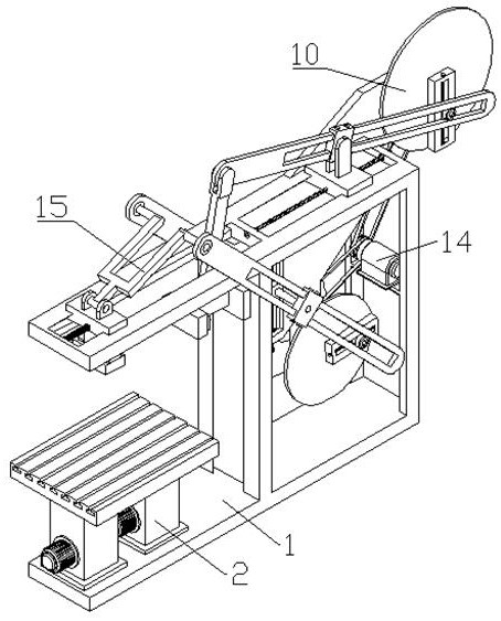
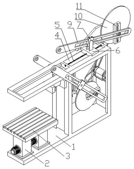
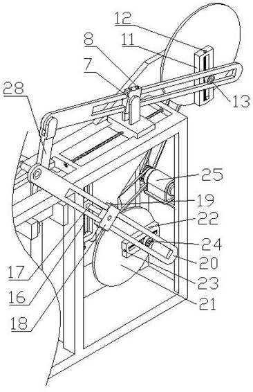
[0016] Such as Figure 1-4 As shown, a grinding device for mechanical processing includes a main body 1, a push rod motor 2, a workbench 3, a No. 1 dovetail groove 4, a No. 1 adjusting screw 5, a No. 1 support slider 6, and a No. 1 fastening slider 7 , No. 1 fastening bolt 8, No. 1 transmission frame 9, upper adjustment disc 10, upper adjustment seat 11, upper adjustment screw rod 12, upper adjustment sliding seat 13, transmission part 14, grinding part 15, the front part of the main body 1 is fixed There are two vertical push rod motors 2, and a horizontal workbench 3 is fixed on the top of the push rods of the two push rod motors 2, and a horizontal No. 1 dovetail groove 4 is opened on the rear upper part of the main body 1. The rear upper part is rotatably connected with a horizontal No. 1 adjusting screw 5 through a bearing, and the rear ...


PUM


Abstract

The invention discloses a grinding device for machining. The grinding device for machining comprises a body, push rod motors, a workbench, a first dovetail groove, a first adjusting screw rod, a first supporting sliding block, a first fastening sliding block, a first fastening bolt, a first transmission frame, an upper adjusting disc, an upper adjusting seat, an upper adjusting screw rod, an upper adjusting sliding seat, a transmission part and a grinding part. The two vertical push rod motors are fixed to the front portion of the body, and the horizontal workbench is fixed to the top ends of push rods of the two push rod motors together. According to the grinding device for machining, by means of rotation of a first speed adjusting motor, two planes can be ground at the same time, the grinding efficiency is directly improved, the probability of surface damage is reduced while the replacement of the workpiece placing position is reduced, and therefore the machining efficiency and the yield are indirectly improved; and the reciprocating grinding amplitude of two grinding blocks can be adjusted by adjusting the positions of the upper adjusting sliding seat and a lower adjusting sliding seat, and meanwhile the purpose of adjusting the reciprocating grinding speed of the two grinding blocks is achieved.

Description

technical field [0001] The invention relates to the field of machining, in particular to a grinding device for machining. Background technique [0002] Grinding is a common machining process. For most workpieces that need to be machined, it is often necessary to use a grinder to grind them. However, traditional grinders can only grind one side of the workpiece at the same time. , but most of the workpieces need to be polished on more than one surface, and the grinding precision requirements of different surfaces are not the same, so while ensuring the processing efficiency, often can only choose to use multiple grinding machines with different grinding precision for grinding, but It still takes a certain amount of time to load and unload the workpiece, and frequent transportation will increase the probability of surface damage that has been polished, which will reduce the yield rate and cause unnecessary losses, highlighting the traditional grinding device. inadequacies. ...

Claims


Application Information

Patent Timeline
Patent Type & Authority Applications(China)
IPC IPC(8): B24B27/02B24B27/00B24B49/00B24B47/16B24B41/06B24B41/02
CPCB24B27/02B24B27/0076B24B49/006B24B47/16B24B41/06B24B41/02Y02P70/10
Inventor 孔凡廷
Owner 枣庄一桐金属制品有限公司
Why Eureka
Try Eureka