Solar mobile charging equipment

A mobile charging and solar energy technology, applied in the field of solar energy, can solve the problems of reducing the power generated by the solar panel, reducing the light of the solar panel, difficult to reach the length of the vehicle with an internal combustion engine, etc., to achieve the effect of increasing the surface area, improving the service life, and increasing the power generation.

Pending Publication Date: 2021-08-24
王珍
View PDF0 Cites 1 Cited by
  • Summary
  • Abstract
  • Description
  • Claims
  • Application Information

AI Technical Summary

Problems solved by technology

[0002] With the popularization of electric vehicles in daily life, more and more people use electric vehicles for travel. When using electric vehicles for long-distance driving, electric vehicles are limited by the current battery technology. The mileage is difficult to reach the internal combustion engine. The length of the car and the number of outdoor charging stations are too small, so the use of solar mobile charging equipment can charge the vehicle in the case of sufficient sunlight during the day, but because the solar charging panel needs an excessively large area to generate enough electricity for electric vehicles When the car is charging, when charging in the Gobi area with large wind and sand, the dust will fall on the outside of the solar panel with the air, reducing the transmittance of the light outside the solar panel, resulting in the light received by the solar panel Reduced, reducing the power generation of solar panels

Method used


Image

  • Solar mobile charging equipment
  • Solar mobile charging equipment
  • Solar mobile charging equipment

Examples


Embodiment 1

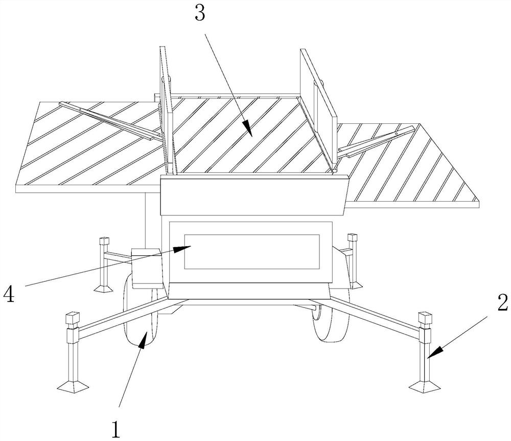
[0028] as attached figure 1 to attach Figure 6 Shown:

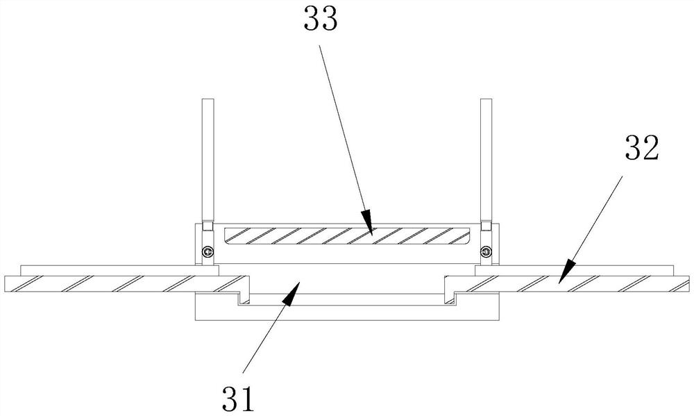
[0029] The invention provides a solar mobile charging device, the structure of which includes a moving wheel 1, a supporting leg 2, a solar device 3, and a charging bin 4. The middle part of the moving wheel 1 is connected to the outer shaft of the solar device 3, and the rear end of the supporting leg 2 It is bolted to the outside of the charging bin 4, and the lower side of the solar device 3 is attached to the upper side of the charging bin 4. The solar device 3 includes a fixed frame 31, a dust sweeper 32, and a top plate 33. The inner side of the fixed frame 31 is connected to the upper side of the charging bin 4. The outer side of the dust sweeping device 32 is fitted with clearance, and the outer side of the top plate 33 is engaged with the upper end of the fixing frame 31 .

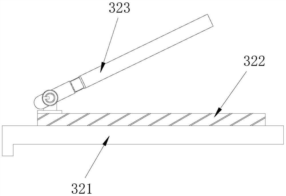
[0030] Wherein, the dust sweeping device 32 includes a solar panel 321, a sweeping rod 322, and a force-bearing plate 323, the upper side...

Embodiment 2

[0037] as attached Figure 7 To attach Figure 9 Shown:

[0038] Wherein, the force receiving plate 323 includes a supporting block 23a, a torsion shaft 23b, and a rotating plate 23c, the upper side of the supporting block 23a is embedded and connected with the middle part of the torsion shaft 23b, and the outer side of the torsion shaft 23b is movable with the lower end of the rotating plate 23c. Together, the inside of the torsion shaft 23b is a helical structure, and the rotating plate 23c can be deflected with the torsion shaft 23b as a fulcrum, so that the force receiving plate 323 can be accommodated by rotation, reducing the space occupancy rate of the force receiving plate 323 .

[0039] Wherein, the rotating plate 23c includes a main plate c1, a cleaning head c2, a connecting rod c3, and a clamping head c4. The lower side of c1 is embedded and connected, and the upper side of the chuck c4 is embedded and connected with the lower side of the connecting rod c3. The shap...


PUM


Abstract

The invention discloses solar mobile charging equipment which structurally comprises moving wheels, supporting legs, a solar device and a charging bin, the middles of the moving wheels are in shaft connection with the outer side of the solar device, the rear ends of the supporting legs are in bolt connection with the outer side of the charging bin, the lower side of the solar device is attached to the upper side of the charging bin, and the solar device comprises a fixing frame, a dust sweeping device and a top plate. The inner side of the fixing frame is in clearance fit with the outer side of the dust sweeping device, the stress plate is blown by wind power to drive the sweeping rods to deflect, when the sweeping rods deflect to the edge, the side supporting rods are driven by inertia to expand outwards to sweep the area outside the rotation angle, the area of sunshine irradiated on the surface of the solar panel is increased, and the power generation power of the solar panel is improved. When wind power is too large, the wind receiving plate can rotate around the center shaft, the wind receiving plate can push the buffering plate to conduct buffering around the rotating shaft during rotation, and finally the center shaft is driven to rotate, so that the situation that too large torque is generated due to too large wind power is prevented, and the service life of the dust sweeping device is prolonged.

Description

technical field [0001] The invention belongs to the field of solar energy, and more specifically, relates to a solar mobile charging device. Background technique [0002] With the popularization of electric vehicles in daily life, more and more people use electric vehicles for travel. When using electric vehicles for long-distance driving, electric vehicles are limited by the current battery technology. The mileage is difficult to reach the internal combustion engine. The length of the car and the number of outdoor charging stations are too small, so the use of solar mobile charging equipment can charge the vehicle in the case of sufficient sunlight during the day, but because the solar charging panel needs an excessively large area to generate enough electricity for electric vehicles When the car is charging, when charging in the Gobi area with large wind and sand, the dust will fall on the outside of the solar panel with the air, reducing the transmittance of the light out...

Claims


Application Information

Patent Timeline
IPC IPC(8): B60L53/30B60L53/51F03D9/20F03D9/32H02J7/35H02S40/10
CPCB60L53/30B60L53/51F03D9/20F03D9/32H02J7/35H02S40/10Y02E10/50Y02E10/72Y02E10/728Y02T10/70Y02T10/7072Y02T90/12
Inventor 王珍
Owner 王珍
Why Eureka
Try Eureka