
Road film paving device for road construction

A film laying device and road construction technology, which is applied in the direction of roads, roads, road repairs, etc., can solve the problems of reducing construction efficiency, being blown by the wind, and the plastic film cannot be closely attached to the road surface, so as to achieve good cleaning effect. Effect of saving water resources

Inactive Publication Date: 2021-08-24
王富玲
View PDF5 Cites 1 Cited by
  • Summary
  • Abstract
  • Description
  • Claims
  • Application Information

AI Technical Summary

Problems solved by technology

[0003] When constructing roads, it is necessary to paste plastic film on the road surface, and then pour concrete on the road surface. However, the existing plastic films are manually applied. Manual film application not only reduces the construction efficiency, but also As a result, the plastic film cannot be closely attached to the road surface, and it is easy to be blown up by the wind before the concrete is poured. At the same time, there will be gravel and other impurities on the road surface before the film is applied, which is easy to tear the plastic film, which will cause the concrete and the layer or the base layer In direct contact, concrete will lose water faster. The strength of concrete requires hydration of cement, but too fast water loss will affect the strength of concrete. For this reason, we propose a road filming device for road construction to solve the above problems

Method used


Image

  • Road film paving device for road construction
  • Road film paving device for road construction
  • Road film paving device for road construction

Examples


Embodiment Construction

[0025] The following will clearly and completely describe the technical solutions in the embodiments of the present invention with reference to the accompanying drawings in the embodiments of the present invention. Obviously, the described embodiments are only some, not all, embodiments of the present invention. Based on the embodiments of the present invention, all other embodiments obtained by persons of ordinary skill in the art without making creative efforts belong to the protection scope of the present invention.

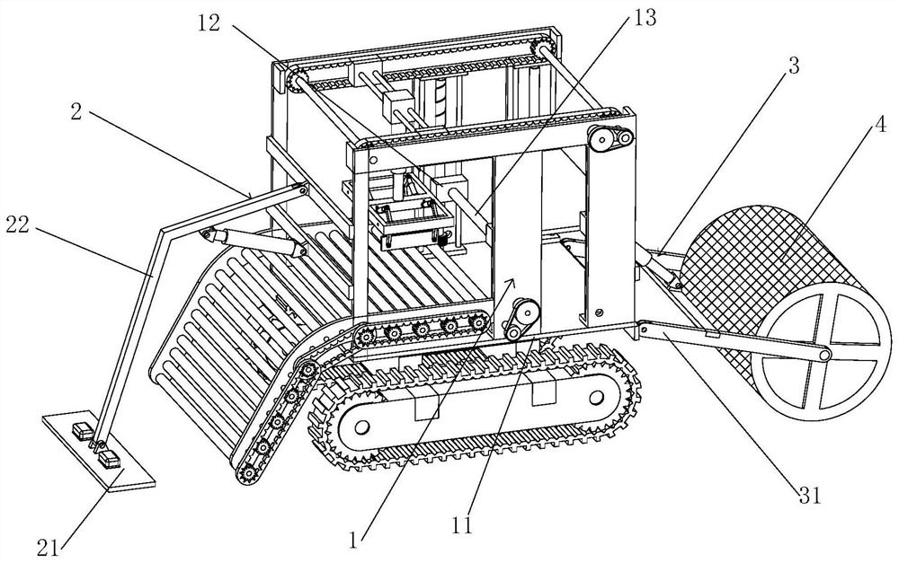
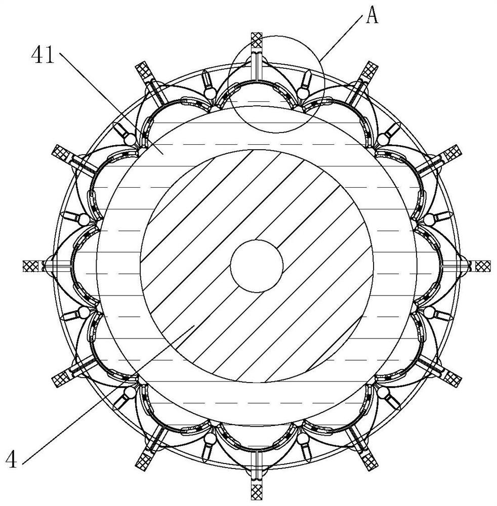
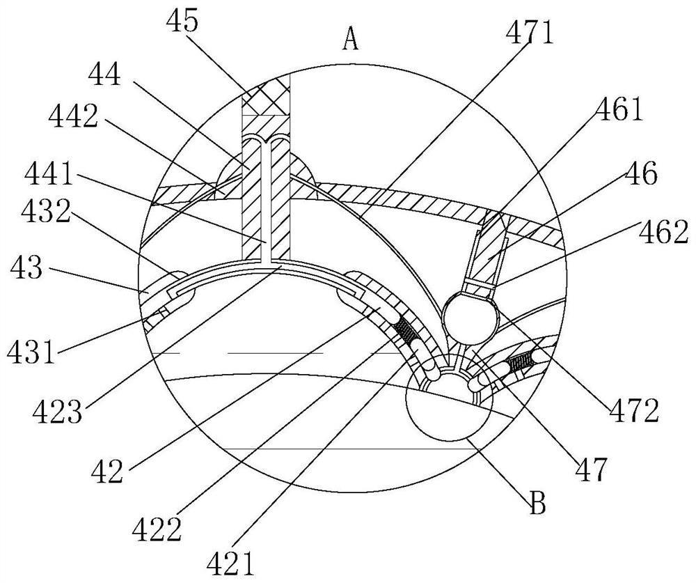
[0026] see Figure 1-6 , the present invention provides a technical solution: a road film-laying device for road construction, including a film-laying machine main body 1, the film-laying machine main body 1 includes a support frame 11, and a movable block 12 is provided slidingly on the inner wall of the support frame 11, and the movable block 12 rotations are provided with a reel 13, the bottom of the support frame 11 is equipped with a walking crawler belt,...


PUM


Abstract

The invention discloses a road film laying device for road construction. The device comprises a film laying machine body. The film laying machine body comprises a supporting frame, movable blocks are arranged on the inner wall of the supporting frame in a sliding mode, a winding drum is rotationally arranged between the movable blocks, a walking crawler belt is installed at the bottom of the supporting frame, and a smoothing mechanism is fixedly installed at one end of the supporting frame and comprises a connecting rod. The connecting rod is fixedly installed at one end of the supporting frame and is in an L shape, a smoothing plate is fixedly installed at the bottom of the connecting rod, and a hydraulic rod is fixedly connected to the bottom of the connecting rod; compared with the prior art, the road surface can be swept through the sweeping brush. Meanwhile, water in the water storage cavity is discharged through the water outlet pipeline, the sweeping brush can be wetted, the sweeping brush has the better cleaning effect, constructors do not need to sprinkle water on the road surface, water resources can be saved, condensed soil blocks on the road surface are scraped away through the scraper, and the construction efficiency is improved. The water loss caused by contact between the concrete and the base layer due to scraping of the plastic film is avoided.

Description

technical field [0001] The invention relates to the technical field of road construction, in particular to a road film laying device for road construction. Background technique [0002] Road engineering refers to the whole process of planning, design, construction, maintenance and management of roads and the engineering entities involved. Like any other category of civil engineering, road engineering has obvious technical, economic and management characteristics. [0003] When constructing roads, it is necessary to paste plastic film on the road surface, and then pour concrete on the road surface. However, the existing plastic films are manually applied. Manual film application not only reduces the construction efficiency, but also As a result, the plastic film cannot be closely attached to the road surface, and it is easy to be blown up by the wind before the concrete is poured. At the same time, there will be gravel and other impurities on the road surface before the film...

Claims


Application Information

Patent Timeline
Patent Type & Authority Applications(China)
IPC IPC(8): E01C19/00E01H1/05E01C23/085
CPCE01C19/00E01H1/05E01C23/085
Inventor 王富玲
Owner 王富玲
Learn More