Automatic road embossing machine

An automatic and engraving technology, which is applied in the direction of engine components, engine lubrication, roads, etc., can solve the problems of unsatisfactory work efficiency, increase the difficulty of workers' operation, and hard work in the process of use, so as to prevent smoke and dust from spreading, improve cutting efficiency, Easy to control effects

Pending Publication Date: 2021-08-24
广西梧州市赢鑫船舶制造有限公司
View PDF13 Cites 1 Cited by
  • Summary
  • Abstract
  • Description
  • Claims
  • Application Information

AI Technical Summary

Problems solved by technology

Existing road engraving machines generally include single-wire cutting machines and multi-wire cutting machines. Single-wire cutting machines can only carve one stripe each time, and require workers who operate the machine to have certain work experience. During the cutting process, workers are required to hold Stabilize the direction so that the texture is straight and parallel to other textures. After one texture is cut, it needs to be re-aligned and re-operated for the next cutting. The labor cost is high and the work efficiency is low.
Although the multi-wire cutting machine can cut multiple parallel textures at the same time, because it cuts multiple parallel textures at the same time each time, in order to keep the carved lines straight, the workers need to exert more force to press down and control the machine. The direction of advancement, which increases the difficulty of operation for workers, the use process is more difficult than single-wire cutting, and the work efficiency still cannot meet the requirements

Method used


Image

  • Automatic road embossing machine
  • Automatic road embossing machine
  • Automatic road embossing machine

Examples


Embodiment Construction

[0026] The present invention will be further described below in conjunction with the specific embodiments in the accompanying drawings.

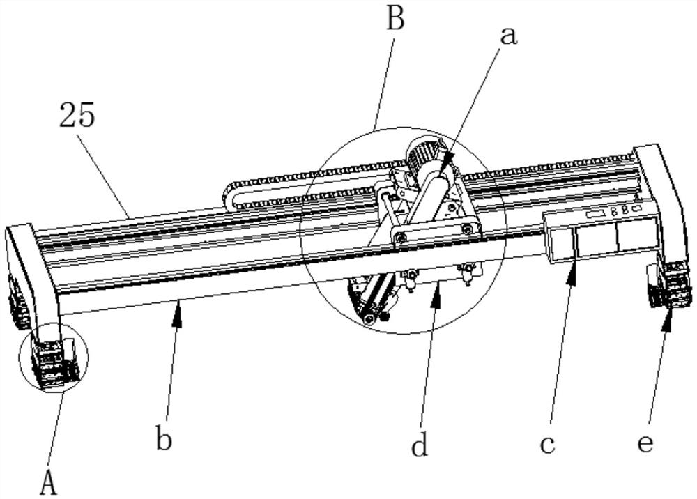
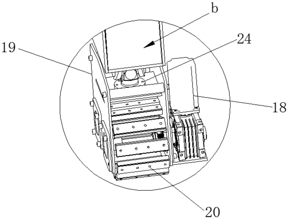
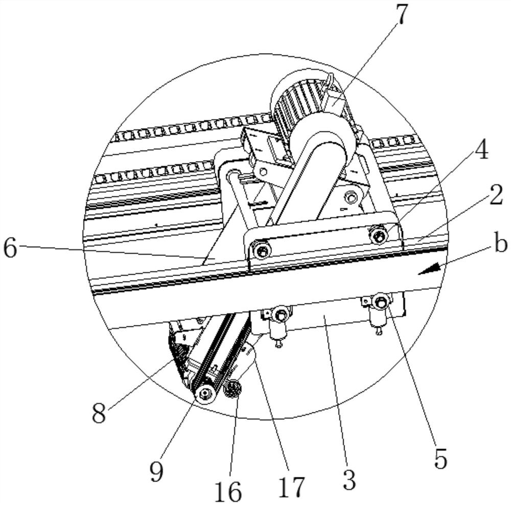
[0027] refer to Figure 1-6 , a road automatic engraving machine of the present invention, including a cutting machine a, also includes an outer frame support b and a controller c, the outer frame support b is a U-shaped frame, a sliding seat d is slidably installed on the outer frame support b, and the sliding The seat d can slide linearly along the outer frame support b, and the first drive assembly that drives the sliding seat d to move horizontally is provided on the outer frame support b. The cutting machine a is rotatably installed on the sliding seat d, and the cutting machine a and the sliding seat d There is a second driving assembly that drives the cutting machine a to rotate, and a plurality of moving seats e are provided at the bottom of the outer frame support b to drive the outer frame support b to move, wherein the cutting mac...


PUM


Abstract

The invention discloses an automatic road embossing machine, belongs to the field of road embossing machines, and solves the problems of high labor intensity and low efficiency of an existing road embossing machine. The embossing machine comprises a cutting machine and further comprises an outer frame support and a controller, a sliding seat is installed on the outer frame support in a sliding mode, a first driving assembly for driving the sliding seat to move horizontally is arranged on the outer frame support, and the cutting machine is rotatably installed on the sliding seat. A second driving assembly for driving the cutting machine to rotate is arranged between the cutting machine and the sliding seat, a plurality of moving seats are arranged at the bottom of the outer frame support, and the cutting machine, the first driving assembly, the second driving assembly and the moving seats are all electrically connected with the controller. According to the automatic road embossing machine, the working efficiency can be effectively improved and the labor intensity can be reduced under the condition that the straight road embossed lines are ensured.

Description

technical field [0001] The present invention relates to road engraving, more specifically, it relates to an automatic road engraving machine. Background technique [0002] During road maintenance or construction, it is necessary to use a road engraving machine to engrave on the cement pavement to increase the friction of the road and prevent vehicles from slipping. Existing road engraving machines generally include single-wire cutting machines and multi-wire cutting machines. Single-wire cutting machines can only carve one stripe each time, and require workers who operate the machine to have certain work experience. During the cutting process, workers are required to hold The direction should be stabilized so that the texture is straight and parallel to other textures. After one texture is cut, it needs to be re-aligned for the next cutting operation. The labor cost is high and the work efficiency is low. Although the multi-wire cutting machine can cut multiple parallel tex...

Claims


Application Information

Patent Timeline
Patent Type & Authority Applications(China)
IPC IPC(8): E01C23/088F16N11/00F16N21/00F25D31/00
CPCE01C23/088F16N11/00F16N21/00F25D31/00
Inventor 麦树雄
Owner 广西梧州市赢鑫船舶制造有限公司
Why Eureka
Try Eureka