
Hydraulic equipment for dismounting and mounting bucket tooth pin shaft

A technology of hydraulic equipment and pin shaft, which is applied to earth moving machines/shovels, construction, etc., can solve problems such as inconvenience, low work efficiency, time-consuming and labor-intensive, etc., and achieve the effects of convenient use, improved efficiency, and good application prospects.

Active Publication Date: 2021-08-24
漳州鑫山航机械有限公司
View PDF5 Cites 1 Cited by
  • Summary
  • Abstract
  • Description
  • Claims
  • Application Information

AI Technical Summary

Problems solved by technology

[0004] In order to overcome the disadvantages of the prior art that the pin shaft installation and disassembly of the bucket teeth of the excavator are manually operated, which will bring great inconvenience to the staff, time-consuming and labor-intensive, and low work efficiency, the present invention provides Provide a compact structure, easy to use, no manual operation, the staff only need to simply operate the power switch to realize the extension or retraction of the front end of the piston of the oil cylinder, and then the pin shaft can be pushed out or pushed in conveniently, thereby improving The hydraulic equipment for dismantling and installing the bucket tooth pin shaft improves the efficiency of dismantling and installing the bucket teeth

Method used


Image

  • Hydraulic equipment for dismounting and mounting bucket tooth pin shaft
  • Hydraulic equipment for dismounting and mounting bucket tooth pin shaft
  • Hydraulic equipment for dismounting and mounting bucket tooth pin shaft

Examples


Embodiment Construction

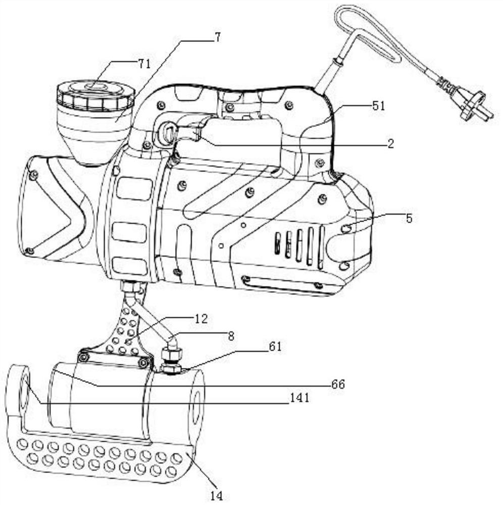
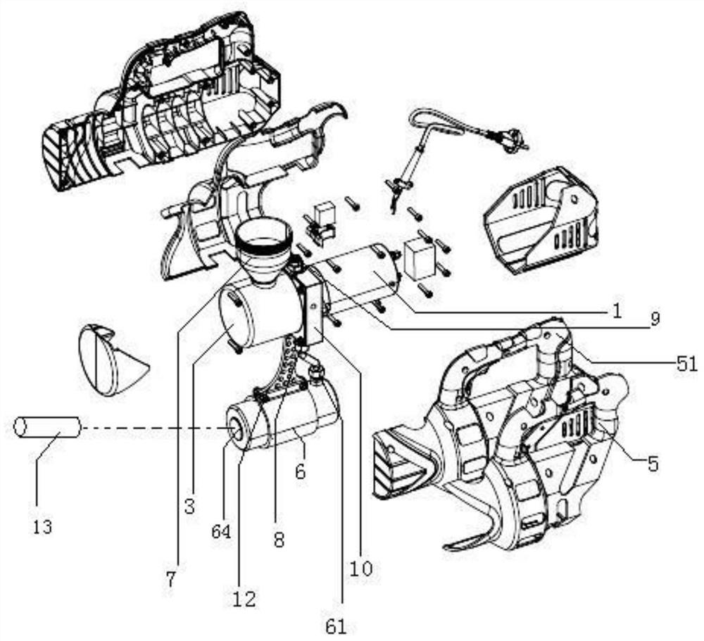
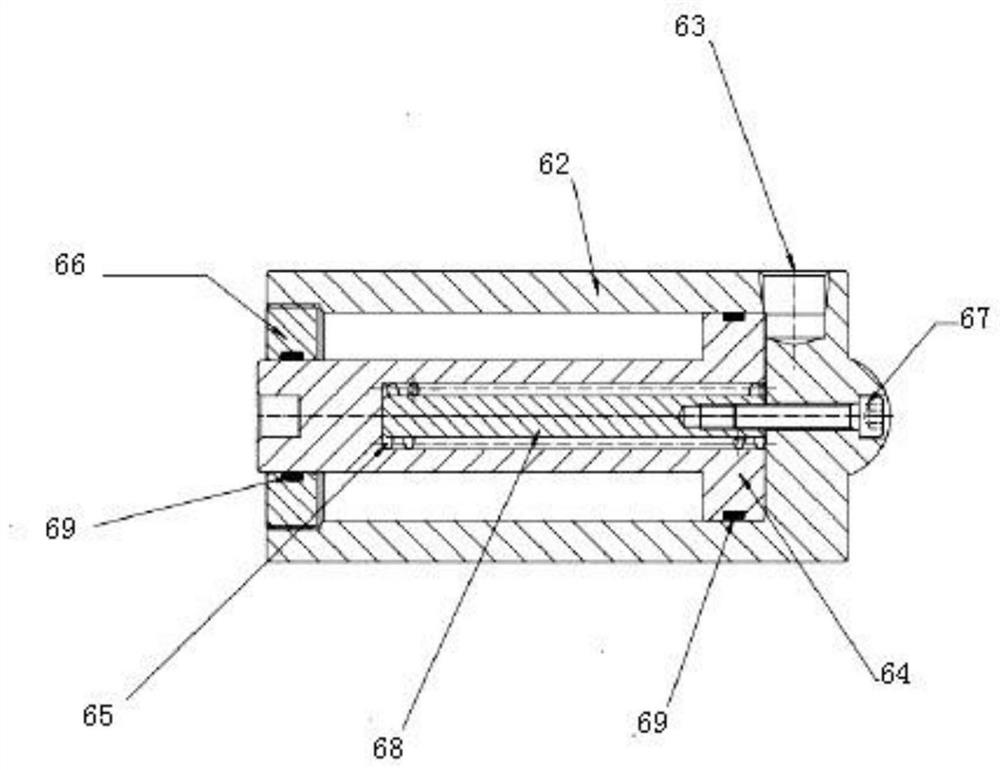
[0021] figure 1 , 2 , 3, 4, 5, 6, and 7, the hydraulic equipment for removing and installing the bucket tooth pin shaft, including DC24V / 800W DC motor 1, dual-position power switch 2, oil drum 3, small bidirectional gear pump 4 , housing 5, oil cylinder 6, conical refueling pot 7, high-pressure oil pipe 8, high-pressure overflow valve 9, oil circuit integrated distribution block 10; the upper middle part of the oil barrel 3 has an oil filling hole with internal thread, and the refueling pot 7 Screw the external thread of the oil pipe in the middle of the lower end into the internal thread of the oil injection hole and install it on the outer upper end of the oil barrel 3; the left end of the cylindrical hollow oil barrel 3 is a closed structure, and the right end is an open structure, and the oil circuit is integrated. The left part of the distribution block 10 is installed on the right outer end of the oil barrel 3 through the screw nut, and the motor 1 is installed on the r...


PUM


Abstract

Hydraulic equipment for dismounting and mounting a bucket tooth pin shaft comprises a motor, a power switch, an oil drum, a bidirectional gear pump, a shell, an oil cylinder, an oil can, a high-pressure oil pipe, an overflow valve and an oil way integration distribution block. The oil can is mounted at the upper end of the oil drum; one side of the oil way integration distribution block is mounted on one side of the oil drum, and the motor is mounted on the other side of the oil way integration distribution block; the bidirectional gear pump is mounted on one side of the oil way integration distribution block, and a power input shaft of the bidirectional gear pump and a power output shaft of the motor are mounted together; the oil drum and the oil cylinder are mounted together; the overflow valve is mounted on the oil way integration distribution block; a lower oil pipe of the oil cylinder and a lower oil inlet and outlet pipe of the oil way integration distribution block are mounted together through an oil pipe; the shell is installed on the outer side of the motor, and the power switch is installed on the shell. The equipment is small and exquisite in structure and convenient to use, a piston of the oil cylinder can move forwards to eject out of or into the bucket tooth pin shaft and move backwards to return to the initial state only by controlling a power switch, so that the bucket tooth dismounting and mounting efficiency is improved.

Description

technical field [0001] The invention relates to the technical field of self-electric dismantling equipment, in particular to hydraulic equipment for disassembling and installing bucket tooth pin shafts. Background technique [0002] In order to improve the excavation efficiency, excavators and other equipment are fixedly equipped with a plurality of bucket teeth at the front end of the bucket at intervals from the distribution pin shaft. In practice, bucket teeth need to be replaced after being used for a period of time due to breakage and wear. Before replacing the bucket teeth, it is necessary to eject the pin shaft from the pin shaft fixing hole of the bucket tooth fixing seat at the front end of the bucket to remove the bucket tooth to be replaced; after replacing the bucket teeth, the pin shaft needs to be pushed out of the pin shaft fixing hole at the front end of the bucket. Push it into the fixing hole, and then fix the new tooth. [0003] In the prior art, since t...

Claims


Application Information

Patent Timeline
Patent Type & Authority Applications(China)
IPC IPC(8): E02F9/00E02F9/28
CPCE02F9/006E02F9/2833E02F9/2891
Inventor 陈俊山
Owner 漳州鑫山航机械有限公司
Learn More