Continuous automatic feeding equipment

A technology of automatic feeding and equipment, applied in the directions of shaking/oscillating/vibrating mixers, dissolving, mixers, etc., can solve the problem of raw materials stuck between two adjacent blades, achieve automatic intermittent feeding, and promote uniformity. Effect

Pending Publication Date: 2021-08-27
CHONGQING THREE GORGES UNIV
View PDF8 Cites 0 Cited by
  • Summary
  • Abstract
  • Description
  • Claims
  • Application Information

AI Technical Summary

Problems solved by technology

[0004] The present invention intends to provide a continuous automatic feeding equipment to solve the problem that the raw materials will be stuck between two adjacent blades during the mixing of various raw materials in the current continuous feeding operation

Method used


Image

  • Continuous automatic feeding equipment
  • Continuous automatic feeding equipment
  • Continuous automatic feeding equipment

Examples


Embodiment 1

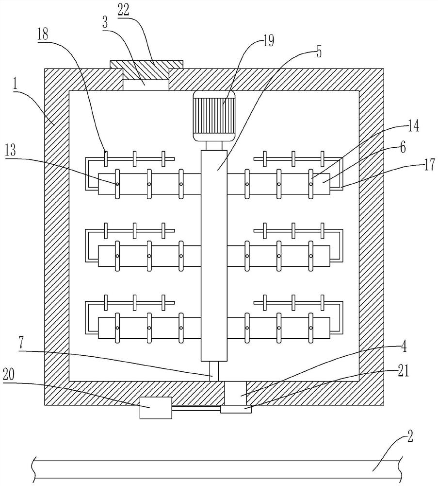
[0034] Basic as attached figure 1 And attached figure 2 Shown: a continuous automatic feeding equipment, including a machine base, a mixing box 1 and a transmission mechanism are fixedly connected to the machine base. The transmission mechanism is a commonly used belt conveyor 2, and the transmission mechanism is located below the mixing box 1.

[0035] The top of the mixing box 1 has a feed port 3, the bottom of the mixing box 1 is provided with a discharge port 4, and the feed port 3 is threadedly connected with a sealing plate 22; the mixing box 1 is provided with a rotating shaft 5 and is used to drive the rotating shaft. 5 rotating power part, the power part is a motor 19 fixedly connected to the inner top of the mixing box 1, and the output shaft of the motor 19 is fixedly connected to the rotating shaft 5. A plurality of blades 6 are affixed on the rotating shaft 5 along the axial direction of the rotating shaft 5, and a round shaft 7 is affixed to the inner bottom of...

Embodiment 2

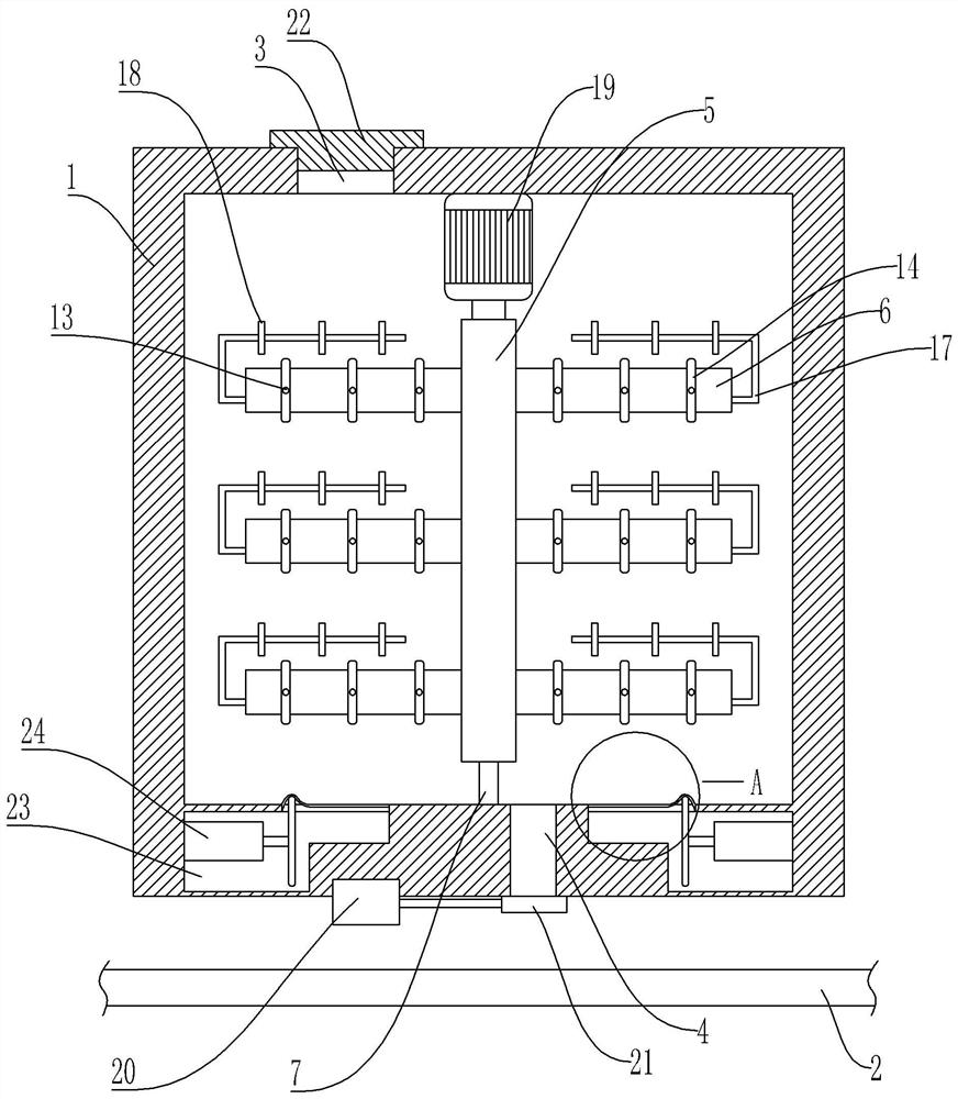
[0046] Basic as attached image 3 And attached Figure 4 As shown: the structure and implementation of Embodiment 2 are basically the same as Embodiment 1, the difference is that: there are horizontal chambers 23 inside both sides of the bottom of the mixing box 1, and the second cylinder is fixed in the horizontal chamber 23 24, and the output shaft of the second cylinder 24 is fixedly connected with a movable block 25; both sides of the bottom of the mixing box 1 are vertically provided with top grooves, and the top groove communicates with the transverse chamber 23, and the top groove is fixedly connected with a movable block 25 extrudes the elastic layer 26 protruding upwards, and in the present embodiment, the elastic layer 26 is a rubber layer.

[0047] The specific implementation process is as follows:

[0048] During the mixing of multiple raw materials, start the second cylinder 24, and the output shaft of the second cylinder 24 drives the movable block 25 to move l...


PUM


Abstract

The invention relates to the technical field of raw material conveying, and discloses continuous automatic feeding equipment . The continuous automatic feeding equipment comprises a machine base, a mixing box and a conveying mechanism are arranged on the machine base, and the conveying mechanism is located below the mixing box; a feeding hole is formed in the top of the mixing box, and a discharging hole is formed in the bottom of the mixing box; a rotating shaft and a power part for driving the rotating shaft to rotate are arranged in the mixing box, a plurality of blades are arranged on the rotating shaft in the axial direction of the rotating shaft, a circular shaft is arranged at the bottom in the mixing box, a circular groove is vertically upwards formed in the bottom of the rotating shaft, and the circular shaft is located in the circular groove; and the continuous automatic feeding equipment also comprises anintermittent mechanism and a linkage mechanism ; the intermittent mechanism is used for controlling opening and closing of the discharging opening, and the linkage mechanism is used for driving raw materials between every two adjacent blades to transversely move when the rotating shaft rotates relative to the circular shaft. According to the scheme, the problem that raw materials are clamped between two adjacent blades during the mixing period of various raw materials in the current continuous feeding operation is mainly solved.

Description

technical field [0001] The invention relates to the technical field of conveying raw materials. Background technique [0002] Fertilizer refers to a class of substances that provide one or more essential nutrient elements for plants, improve soil properties, and increase soil fertility levels. It is one of the material bases of agricultural production. [0003] At present, fertilizer is made by mixing multiple raw materials, and then the fertilizer is transferred to the bag and sent out to form a continuous feeding operation; among them, the traditional mixing method is to put multiple raw materials into the mixing tank, and then use the mixing structure Mix various raw materials in the mixing tank; in the actual operation process, only a single mixing structure is installed in the existing mixing tank. The mixing structure includes a rotating shaft and multiple blades arranged along the axial direction of the rotating shaft. The rotating shaft passes through the power mecha...

Claims


Application Information

Patent Timeline
Patent Type & Authority Applications(China)
IPC IPC(8): B01F11/00
CPCB01F31/44B01F2101/32
Inventor 刘利利陈才
Owner CHONGQING THREE GORGES UNIV
Why Eureka
Try Eureka