Impurity separation treatment equipment for building waste

A technology for separation and treatment of construction waste, applied in solid separation, grain treatment, screening, etc., which can solve the problems of heavy workload and slow collection speed

Inactive Publication Date: 2021-08-27
深圳市信誉鑫环保科技有限公司
View PDF9 Cites 6 Cited by
  • Summary
  • Abstract
  • Description
  • Claims
  • Application Information

AI Technical Summary

Problems solved by technology

[0005] In order to overcome the relatively hard concrete, the manual hand-held hammer is used to beat the collection speed slowly, and after the waste separation is completed, people need to clean up the steel bars and gravel separately, which makes the workload larger. Technical problems: Provide an impurity separation and treatment equipment for construction waste that can automatically separate and screen construction waste

Method used


Image

  • Impurity separation treatment equipment for building waste
  • Impurity separation treatment equipment for building waste
  • Impurity separation treatment equipment for building waste

Examples


Embodiment 1

[0035] Impurity separation treatment equipment for building waste, such as Figure 1-9 As shown, a support frame 1, a housing 2, a screen 3, a pulverizing mechanism 4, a screening mechanism 5, a transfer mechanism 6, and a pusher 7 are provided, and the top portion of the support frame 1 is provided, and the housing 2 is inside the right side. The sliding type is provided with a screen 3, and a pulverizing mechanism 4 is provided on the right side of the housing 2, and the screen 3 and the pulverizing mechanism 4 are provided with a screening mechanism 5, and the housing 2 is provided with a transport mechanism 6, and the housing 2 is provided. There is a push mechanism 7.

[0036] The pulverizing mechanism 4 includes a first motor 40, a rotating shaft 41, a first gear 42, and a crushing roller 43, and a first motor 40 is provided on the right side of the housing 2, and the axis of the housing 2 has a rotation shaft 41, The output shaft of the first motor 40 is coupled to the rotat...

Embodiment 2

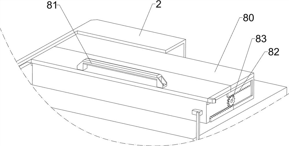
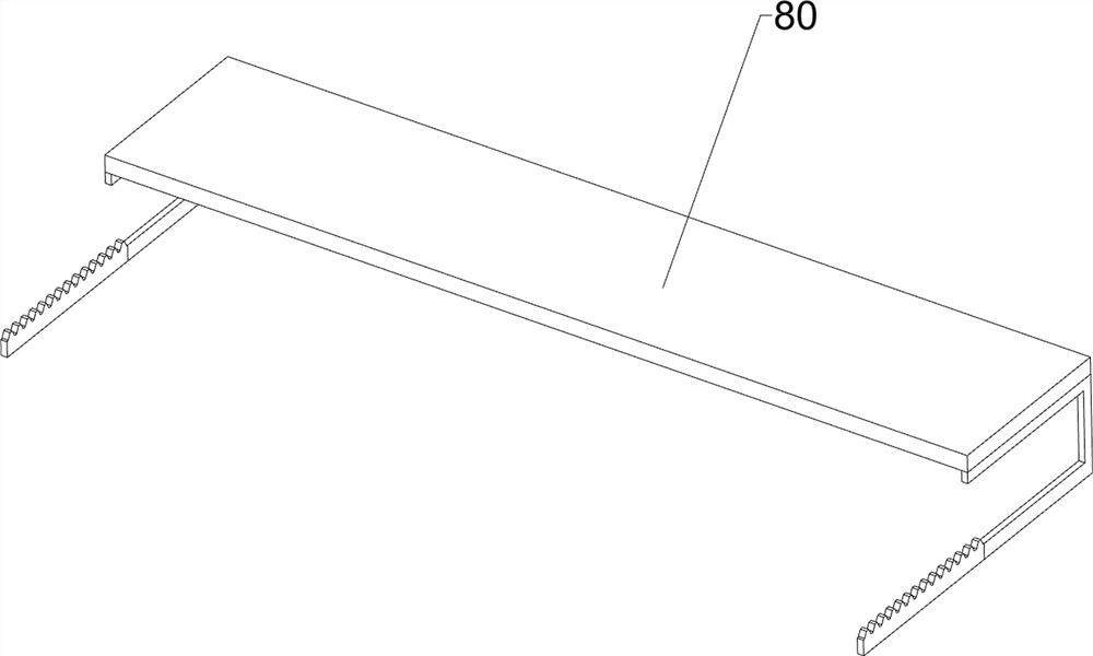
[0044] On the basis of Example 1, such as figure 1 , image 3 , Figure 10 , Figure 11 , Figure 12 , Figure 13 , Figure 14 with Figure 15 The opening and closing assembly 8 is also included, and the opening and closing assembly 8 includes a cover plate 80, a grip 81, a second rack 82, and a second gear 83, and the top and rear symmetry sliding in the top right side of the housing 2 are provided with a cover plate. 80. The front side of the front side of the front side is provided with a grip 81, and the right side of the top right side of the housing 2 is provided with a second gear 83, and the second rack 82 is provided on both sides of the cover plate 80. The second rack 82 is engaged with the second gear 83.

[0045] The user moves toward the front side of the front side by grip 81, drives the upper side of the two second rack 82 to move on the front side, passing two second racks on the upper side. 82 is engaged with the second gear 83, thereby engage the two second rack 82 of t...


PUM


Abstract

The invention relates to treatment equipment, in particular to impurity separation treatment equipment for building waste. According to the impurity separation treatment equipment for the building waste, the building waste can be automatically separated and screened. The impurity separation treatment equipment for the building waste comprises a supporting frame, a shell, a screen, a smashing mechanism, a screening mechanism, a conveying mechanism and a pushing mechanism, the shell is arranged at the top of the supporting frame, the screen is arranged on one side in the shell in a sliding mode, the smashing mechanism is arranged on the side, close to the screen, of the shell, the screening mechanism is arranged between the screen and the smashing mechanism, the conveying mechanism is arranged on the shell, and the pushing mechanism is arranged on the rear side of the shell. Broken stones screened by the screen can fall down on a crawler belt, the crawler belt rotates, and under the action of a limiting block, the crawler belt can convey the broken stones to the left side to an opening of the shell, so that the broken stones can be collected and cleaned in a unified manner.

Description

Technical field [0001] The present invention relates to a processing apparatus, and more particularly to an impurity separation treatment apparatus for building waste. Background technique [0002] Building waste refers to construction, construction units or individuals to build, lay or dismantle all kinds of buildings, structures, pipe networks, etc., have been placed, abandoned and other waste. [0003] Due to the concrete and steel bars in the building waste, the user can collect the steel bars in the waste to carry out the secondary utilization, and people generally place the waste on the ground, thereby manually hitting the hammer, and thus scrap The concrete is knocking, revealing the steel bars, in turn, can be collected. Since the concrete is stronger, it is slow to hit the hammer by artificial hand, so that the collection speed is slow, and after the waste is separated, it needs to clean the steel and gravel, so that the workload is large. [0004] Therefore, it is desir...

Claims


Application Information

Patent Timeline
Patent Type & Authority Applications(China)
IPC IPC(8): B02C4/08B02C23/10B07B1/28B02C4/28B07B1/42B07B1/52
CPCB02C4/08B02C23/10B07B1/28B07B1/42B07B1/526B02C4/286B02C4/28B02C2201/02
Inventor 陈飞飞
Owner 深圳市信誉鑫环保科技有限公司
Why Eureka
Try Eureka