High-speed filling machine

A filling machine, high-speed technology, applied in the field of pharmaceutical packaging equipment, can solve the problems of difficulty in maintaining high-speed filling state, single running trajectory of filling components, and reducing the continuity of filling production, so as to improve the uniformity of feeding and dispersion, The effect of reducing the need for manual feeding and improving the balance of clamping

Active Publication Date: 2021-08-27
上海拓达机电设备有限公司
View PDF9 Cites 4 Cited by
  • Summary
  • Abstract
  • Description
  • Claims
  • Application Information

AI Technical Summary

Problems solved by technology

[0003] In view of the related technologies mentioned above, the inventor believes that the running track of the filling assembly is single, and the filling assembly can only reciprocate back and forth between the bottles at the front and rear positions In terms of filling, the moving speed of the filling component and the running speed of the bottle need to be coordinated and coordinated, and it needs to be set according to the filling speed, otherwise once the filling component is moving forward, the bottle at the front position will be tracked and filled When there is a lag or error, it is too late to reset and fill the bottle at the rear position, and a large number of empty bottles without filling will be transferred to the subsequent process, or the filling component is reset too quickly, and the filling The operation is not complete, the filling volume of the bottle is not up to the standard, it is difficult to maintain the high-speed filling state, which greatly reduces the continuity of filling production

Method used


Image

  • High-speed filling machine
  • High-speed filling machine
  • High-speed filling machine

Examples


Embodiment Construction

[0066] The following combined with the accompanying drawings Figure 1-Figure 13 The application is described in further detail.

[0067] The embodiment of the present application discloses a high-speed filling machine.

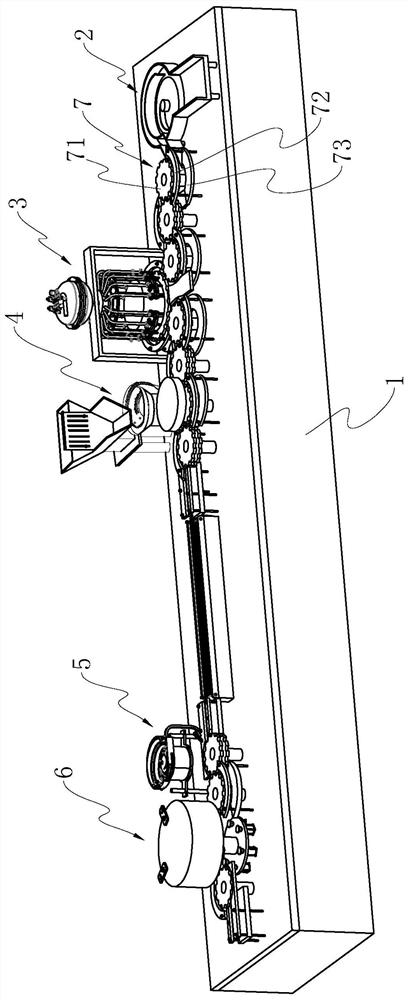
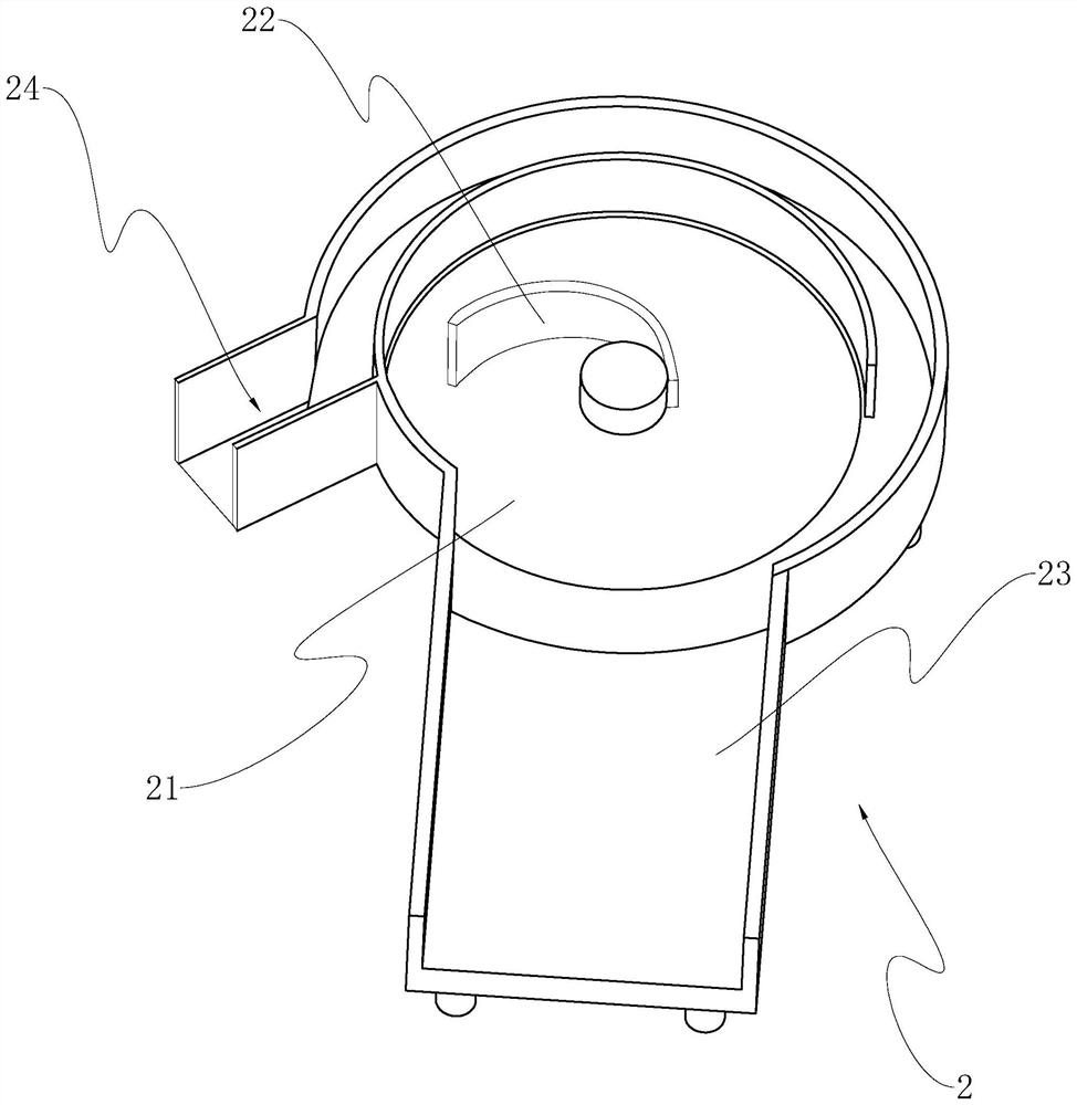
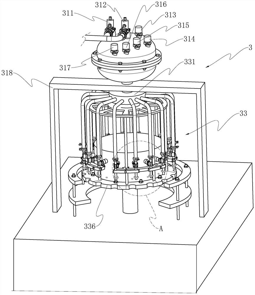
[0068] refer to figure 1 , a high-speed filling machine, including a workbench 1 and a control host, the workbench is provided with a bottle unscrambling assembly 2, a filling machine 3, a plugging assembly 4, a capping machine 5 and a capping machine in sequence along the running path of the bottle body 6. Each process device is connected by a bottle transport assembly 7. The bottle transport assembly 7 includes a bottle transport turntable 71 and a bottle transport guide plate 72 arranged on one side of the bottle transport turntable. The bottle transport guide plate 72 is provided with a bottle inlet and outlet The gap of the bottle is also provided with a clamping groove on the circumference of the bottle transporting turntable 71, the bottle transport...


PUM


Abstract

The invention relates to a high-speed filling machine. The high-speed filling machine comprises a workbench and a filling machine body arranged on the workbench. The filling machine body comprises a liquid storage tank, a filling assembly arranged on a liquid outlet of the liquid storage tank, and a control host. The filling assembly comprises a multi-pass rotating connector arranged at the liquid outlet, filling pipes connected to the multi-pass rotating connector, filling needles arranged on the filling pipes, a filling control valve, a filling rotary disc assembly arranged below the filling needles and used for bottle body transferring, a rotating support arranged between the filling rotating disc assembly and the multi-pass rotating connector, and a driving motor driving the rotating support to rotate. The filling rotating disc assembly is provided with filling stations which are distributed in an annular array mode, the filling pipes and the filling stations are arranged in a one-to-one correspondence mode, and the filling needles are located over the filling stations. Filling photoelectric sensing assemblies corresponding to the filling stations are arranged on the rotating support and connected with the data end of the control host, and the filling control valve and the driving motor are controlled by the control host. The high-speed filling machine has the effect of improving the continuity of the high-speed filling production.

Description

technical field [0001] The present application relates to the technical field of medical packaging equipment, in particular to a high-speed filling machine. Background technique [0002] In the production and packaging process of sterile drugs, drug filling is required, and filling machines are commonly used filling equipment in the filling process. In the related art, the filling machine includes a liquid storage tank, a filling assembly connected to the liquid outlet of the liquid storage tank, and a filling station. When the bottle is transported to the filling station, it stops to wait for the filling of the filling assembly. After the filling operation of the filling component for the bottle body is completed, the bottle body is re-run to be transported to the next packaging process. The intermittent filling method takes a lot of time for filling, which reduces the continuity of filling production and reduces production efficiency. In order to solve the aforementioned...

Claims


Application Information

Patent Timeline
Patent Type & Authority Applications(China)
IPC IPC(8): B67C3/24B67C3/26B67C3/00B67C3/20
CPCB67C3/24B67C3/26B67C3/007B67C3/20
Inventor 仇志敏
Owner 上海拓达机电设备有限公司
Why Eureka
Try Eureka