
Building concrete slab strength detection device

A concrete slab and strength detection technology, which is applied in the direction of measuring device, strength characteristics, and the use of stable tension/pressure test material strength, etc., can solve problems such as inconvenient operation, collapse, concrete fracture, etc., to reduce the solidification time, Accelerate the speed of detection and the effect of coagulation

Pending Publication Date: 2021-08-27
胡斯楞
View PDF0 Cites 1 Cited by
  • Summary
  • Abstract
  • Description
  • Claims
  • Application Information

AI Technical Summary

Problems solved by technology

[0002] In building construction, concrete slabs are indispensable. Concrete slabs are used in many places during house construction, and the quality of this concrete slab is not easy to know intuitively. If the strength of concrete is poor, it will easily affect the construction. The quality of the building makes the whole building collapse, and some directly use concrete to pour the wall. After the pouring is completed, it is not easy to detect the strength of the wall. If the concrete is mixed with other impurities, it is also easy to use in the subsequent use process. It is more dangerous to break the concrete, and it is especially important for the strength detection of concrete. However, the existing electronic instruments are generally used for detection, which is inconvenient for the initial contact personnel. Therefore, it is urgent to design a strength detection device for concrete slabs for construction. To solve the detection problem of concrete slab strength

Method used


Image

  • Building concrete slab strength detection device
  • Building concrete slab strength detection device
  • Building concrete slab strength detection device

Examples


Embodiment Construction

[0017] The following will clearly and completely describe the technical solutions in the embodiments of the present invention with reference to the accompanying drawings in the embodiments of the present invention. Obviously, the described embodiments are only some, not all, embodiments of the present invention. Based on the embodiments of the present invention, all other embodiments obtained by persons of ordinary skill in the art without making creative efforts belong to the protection scope of the present invention.

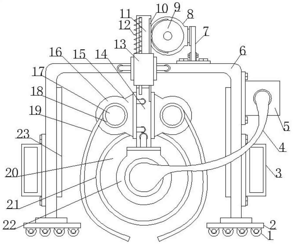
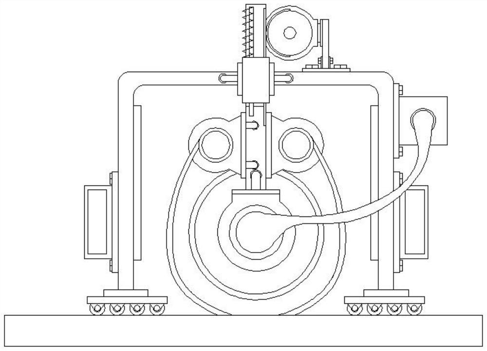
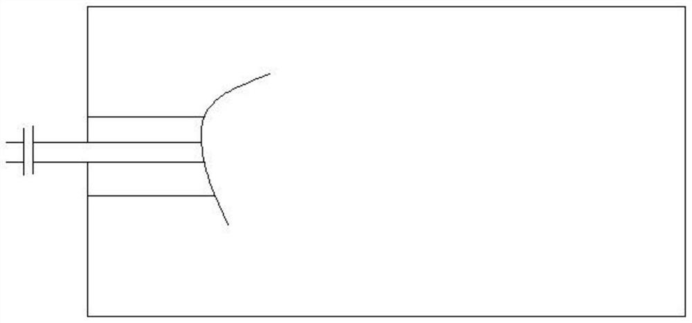
[0018] see Figure 1-3 , the present invention provides a technical solution:

[0019] A concrete slab strength detection device for construction, comprising a support frame 6, a base plate 2 is symmetrically installed at the bottom of the support frame 6, universal wheels 1 are uniformly installed on the bottom surface of the base plate 2, and the left and right sides of the support frame 6 are symmetrical A handle 3 is installed, a support rod 7 is fixedly ...


PUM


Abstract

The invention aims to solve the problem of concrete strength detection, and discloses a building concrete slab strength detection device which comprises a support frame. Bottom plates are symmetrically mounted at the bottom end of the support frame, universal wheels are uniformly mounted on the bottom surfaces of the bottom plates, handles are symmetrically mounted on the left and right side surfaces of the support frame, a support rod is fixedly installed on the right side of the upper surface of the support frame, a first motor is fixedly installed at the top end of the support rod, a gear is installed in the middle of the first motor, a sleeve is fixedly installed in the middle of the top end of the support frame, a sliding frame is sleeved with the sleeve, a rack is welded to the right side face of the sliding frame, the left side wall of the sliding frame is sleeved with a spiral spring, a connecting rod is fixedly installed at the lower end of the sliding frame, a connecting ring is fixedly connected to the lower end of the connecting rod, and a pressing cylinder is installed in the middle of the connecting ring. The pull rope is reasonably poured in the concrete layer, and then the visual detection of the quality of the concrete slab is realized by pulling the pull rope.

Description

technical field [0001] The invention relates to the field of concrete slab detection, in particular to a device for detecting the strength of a concrete slab for construction. Background technique [0002] In building construction, concrete slabs are indispensable. Concrete slabs are used in many places during house construction, and the quality of this concrete slab is not easy to know intuitively. If the strength of concrete is poor, it will easily affect the construction. The quality of the building makes the whole building collapse, and some directly use concrete to pour the wall. After the pouring is completed, it is not easy to detect the strength of the wall. If the concrete is mixed with other impurities, it is also easy to use in the subsequent use process. It is more dangerous to break the concrete, and it is especially important for the strength detection of concrete. However, the existing electronic instruments are generally used for detection, which is inconveni...

Claims


Application Information

Patent Timeline
Patent Type & Authority Applications(China)
IPC IPC(8): G01N3/08G01N3/02
CPCG01N3/08G01N3/02G01N2203/0017
Inventor 胡斯楞
Owner 胡斯楞
Learn More