Rapid exhaust system of air pressure therapy apparatus

An air pressure and exhaust system technology, which is applied in the field of therapeutic equipment, can solve the problems of long exhaust time of exhaust airbags, etc., and achieve the effects of easy daily maintenance, reliable performance, and free and simple selection

Inactive Publication Date: 2018-11-30
泸州市龙马潭区鑫泉泡沫塑料有限责任公司
View PDF0 Cites 2 Cited by
  • Summary
  • Abstract
  • Description
  • Claims
  • Application Information

AI Technical Summary

Problems solved by technology

[0004] The purpose of the present invention is to provide a rapid exhaust system of an air pressure therapy instrument with the characteristics of rapid exhaust in order to solve the problem of long exhaust time of the existing exhaust air bag

Method used


Image

  • Rapid exhaust system of air pressure therapy apparatus

Examples


Embodiment example 1

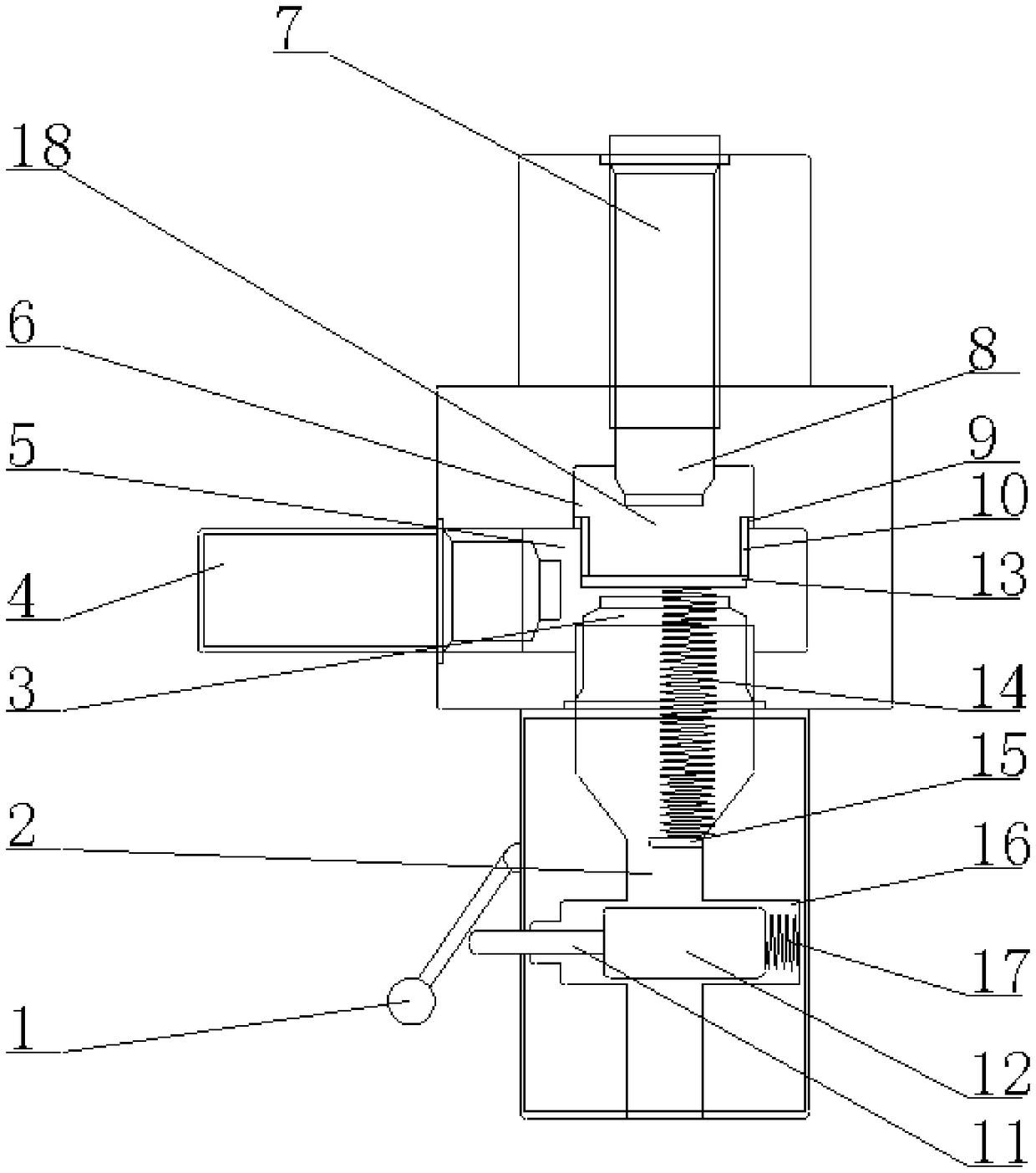
[0025] Implementation Case 1: A rapid exhaust system for an air pressure therapy instrument, including a cavity 18, the upper end of which is connected to an air intake pipe 7, and the air intake pipe 7 extends into the cavity 18 to form a first passageway. Cavity 6, the lower end of the cavity 18 is provided with an exhaust pipe 2, the left side of the cavity 18 is provided with an air guide tube 4, and the air guide tube 4 extends into the guide cavity body 18 to form a second through cavity 5, The exhaust pipe 2 extends into the cavity 18 to form a third through cavity 3, and a sealing diaphragm 13 is arranged between the third through cavity 3 and the first through cavity 6, and the sealing diaphragm 13 A sliding assembly is arranged between the inner wall of the cavity 18 , and the intake pipe 7 , the exhaust pipe 2 and the air guide tube 4 are all provided with protrusions 8 protruding from the cavity 18 .

[0026] The lower end of the sealing diaphragm 13 is connected w...

Embodiment example 2

[0030] Implementation Case 2: If figure 1 As shown, this implementation is further optimized on the basis of Embodiment 1. This embodiment focuses on the improvements compared with Embodiment 1, and the similarities will not be repeated. The control assembly includes a second spring 17, a sealing Block 12 and transmission rod 11, the lower end of the exhaust pipe 2 is provided with a control groove 16, the inner wall of the control groove 16 is connected with the right end of the second spring 17, and the left end of the second spring 17 is connected with the right end of the second spring 17. The sealing block 12 is connected, and the sealing block 12 is connected with the transmission rod 11, and the transmission rod 11 stretches out of the exhaust pipe 2, and the exhaust pipe 2 is provided with a rotary connection for pressing the transmission rod 11. Rod 1, the user presses the pressure rod 1, so that the pressure rod 1 presses the transmission rod 11, and the transmission...

Embodiment example 3

[0031] Implementation case three: if figure 1 As shown, this implementation is further optimized on the basis of Embodiment 1. This embodiment focuses on the improvements compared with Embodiment 1, and the similarities will not be repeated. The connecting post 10 of the sheet 13, the bump provided on the connecting post 10 and the chute on the inner wall of the cavity 18 that is compatible with the bump, the sealing diaphragm 13 is connected with the connecting post 10, and passes through the protrusion on the connecting post 10 8 so that the chute on the inner wall of the cavity 18 moves up and down.


PUM


Abstract

The invention discloses a rapid exhaust system of an air pressure therapy apparatus, and belongs to the technical field of a therapy apparatus. The rapid exhaust system of the air pressure therapy apparatus aims at solving the problem that the time of an existing exhaust airbag exhausting is long. The rapid exhaust system of the air pressure therapy apparatus includes a cavity. The rapid exhaust system of the air pressure therapy apparatus is characterized in that the upper end of the cavity is connected with an air inlet pipe, the air inlet pipe extends into the cavity to form a first throughcavity, the lower end of the cavity is provided with an exhaust pipe, the left side of the cavity is provided with a gas-guide pipe, the gas-guide pipe extends into the cavity to form a second through cavity, the exhaust pipe extends into the cavity to form a third through cavity, a sealing diaphragm is disposed between the third through cavity and the first through cavity, a sliding assembly isdisposed between the sealing diaphragm and an inner wall of the cavity, the lower end of the sealing diaphragm is connected with a first spring, the lower end of the first spring is fixedly connectedwith a fixing column, the fixing column is fixedly connected to the inner wall of the exhaust pipe, and the exhaust pipe is provided with a control assembly.

Description

technical field [0001] The invention belongs to the technical field of therapeutic instruments, and in particular relates to a rapid exhaust system of an air pressure therapeutic instrument. Background technique [0002] The air wave manometer is also called circulation pressure therapy device, gradient pressure therapy device, extremity circulation device or pressure antithrombotic pump. The air wave pressure therapy instrument mainly inflates and deflates the multi-cavity airbags in order to form a circulatory pressure on the limbs and tissues, and squeezes the limbs from the distal end to the proximal end of the limbs uniformly and orderly to promote blood and blood circulation. The flow of lymph and the effect of improving microcirculation can accelerate the return of limb tissue fluid, help prevent the formation of thrombus and limb edema, and can directly or indirectly treat many diseases related to blood lymphatic circulation. [0003] When the multi-chamber airbags ...

Claims


Application Information

Patent Timeline
Patent Type & Authority Applications(China)
IPC IPC(8): A61H9/00F16K24/00
CPCA61H9/005F16K24/00
Inventor 肖启
Owner 泸州市龙马潭区鑫泉泡沫塑料有限责任公司
Why Eureka
Try Eureka