Optical fiber cutting device for optical fiber fusion splicer

A technology of optical fiber fusion splicing machine and cutting device, which is applied in the direction of optical waveguide coupling, etc., can solve the problems of affecting the sliding of cutting blades, reducing cutting quality, time-consuming and labor-intensive, etc., so as to improve the cleaning effect, improve work efficiency, and avoid secondary contact. Effect

Pending Publication Date: 2021-08-27
解维涛
View PDF0 Cites 0 Cited by
  • Summary
  • Abstract
  • Description
  • Claims
  • Application Information

AI Technical Summary

Problems solved by technology

[0003] And during the cutting process, the cut waste fiber shavings can easily enter the cutting device, and long-term accumulation will directly affect the sliding of the cutting blade and reduce the cutting quality
At the same time, the bare optical fiber is usually made of high-purity quartz glass, which has strong hardness and small diameter. After the cutting and welding process is completed, it is necessary to clean the waste optical fiber shavings falling outside the cutting device, which is time-consuming and laborious.

Method used


Image

  • Optical fiber cutting device for optical fiber fusion splicer
  • Optical fiber cutting device for optical fiber fusion splicer
  • Optical fiber cutting device for optical fiber fusion splicer

Examples


Embodiment Construction

[0040] In order to make the purpose, technical solutions and advantages of the embodiments of the present invention more clear, the technical solutions in the embodiments of the present invention will be clearly and completely described below in conjunction with the accompanying drawings in the embodiments of the present invention. Obviously, the described embodiments It is a part of embodiments of the present invention, but not all embodiments. Based on the embodiments of the present invention, all other embodiments obtained by persons of ordinary skill in the art without making creative efforts belong to the protection scope of the present invention.

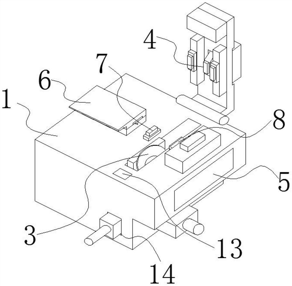
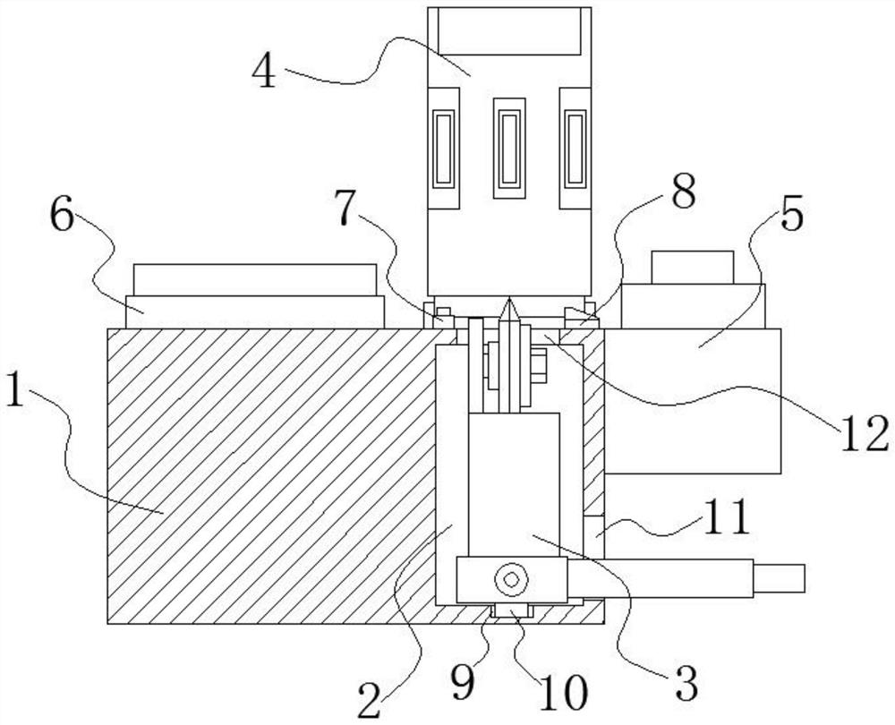
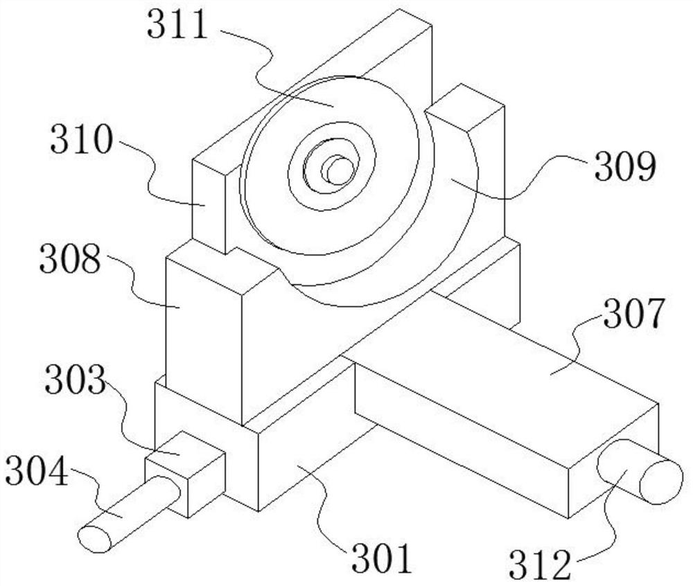
[0041] An embodiment of the present invention provides an optical fiber cutting device for an optical fiber fusion splicer. The cutting device includes a base 1 , a cutting assembly 3 , a platen assembly 4 and a cleaning assembly 5 . Exemplary, such as figure 1 and figure 2 As shown, the base 1 is provided with an inner ch...


PUM


Abstract

The invention relates to the technical field of optical fiber fusion splicer corollary equipment, in particular to an optical fiber cutting device for an optical fiber fusion splicer. The cutting device comprises a base, a cutting assembly, a pressing plate assembly, a cleaning assembly, a first gasket and a second gasket, wherein the cutting assembly is connected into the base in a sliding mode, and the top of the cutting assembly penetrates to the position above the base; a main body of the pressing plate assembly is hinged to the edge of one end of the top of the base; the cleaning assembly comprises a cleaning box, a cleaning box upper cover, an inclined panel, a lifting rod and a scrap shifting head; the cleaning box is fixedly mounted on the outer wall of one side of the base; and the cleaning box upper cover is communicated with the top of the cleaning box, a scrap inlet is formed in the side wall, which is close to the second gasket, of the cleaning box upper cover, and the inclined panel is installed on the scrap inlet. The working efficiency can be improved, and the installation and maintenance time can be shortened.

Description

technical field [0001] The invention belongs to the technical field of supporting equipment for an optical fiber fusion splicer, and in particular relates to an optical fiber cutting device for an optical fiber fusion splicer. Background technique [0002] Before splicing the bare optical fiber, it is necessary to use a cutting device to cut its end face flat. In order to ensure the flatness of the end face, there are high requirements for the performance of the cutting device. [0003] And in the cutting process, the cut waste fiber shavings are easy to enter the inside of the cutting device, and long-term accumulation will directly affect the sliding of the cutting blade and reduce the cutting quality. At the same time, the bare optical fiber is usually made of high-purity quartz glass, which has strong hardness and small diameter. After the cutting and welding process is completed, it is necessary to clean the waste optical fiber shavings falling outside the cutting devi...

Claims


Application Information

Patent Timeline
Patent Type & Authority Applications(China)
IPC IPC(8): G02B6/25
CPCG02B6/25
Inventor 解维涛
Owner 解维涛
Why Eureka
Try Eureka