A cable tray for rail vehicle end

A technology for rail vehicles and cable trays, which is applied to the field of cable trays at the end of rail vehicles, can solve the problems of inconvenient separation of left and right line pipelines, poor structural stability of hangers, easy rusting of support rods, etc. The effect of low production cost, easy installation, use and maintenance

Active Publication Date: 2022-04-26
HUNAN LIANCHENG TRACK EQUIP CO LTD +1
View PDF11 Cites 0 Cited by
  • Summary
  • Abstract
  • Description
  • Claims
  • Application Information

AI Technical Summary

Problems solved by technology

However, there are still some problems in the existing way of using support rods
For example, this kind of support method is not beautiful, it is not convenient to separate the left and right lines, and it needs to drill and tap the key connectors for installation, which poses hidden dangers to the connectors
In addition, after a long time of use, the rotating part of the support rod is prone to rust, which will cause the rotation to stick
In addition, the structure of the hanger used in the existing scheme pipeline is poor in stability, and it is easy to shake during work, causing abnormal noise to be transmitted into the compartment

Method used


Image

  • A cable tray for rail vehicle end
  • A cable tray for rail vehicle end
  • A cable tray for rail vehicle end

Examples


Embodiment Construction

[0025] The present invention is introduced below by accompanying drawing.

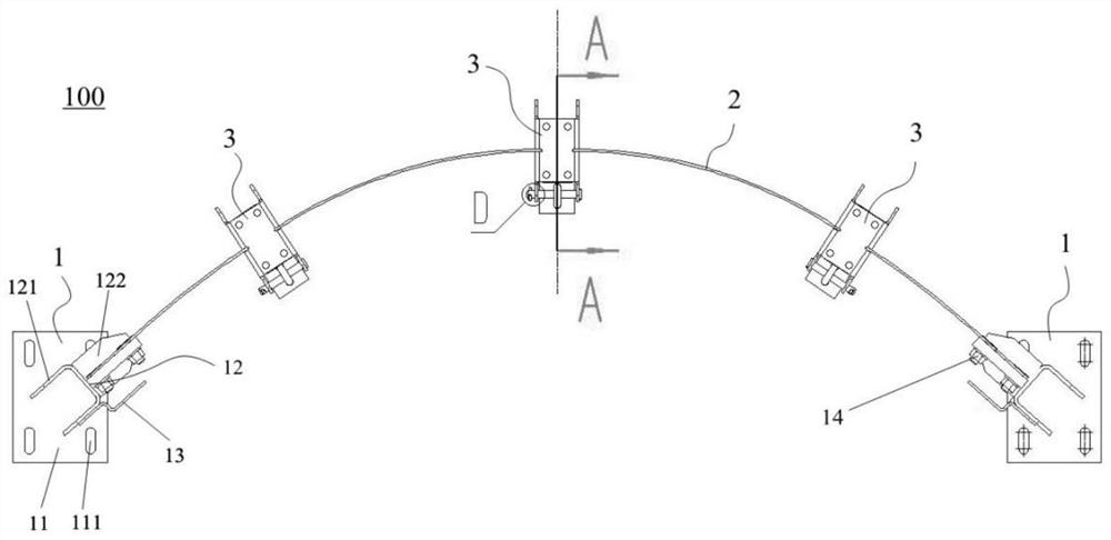
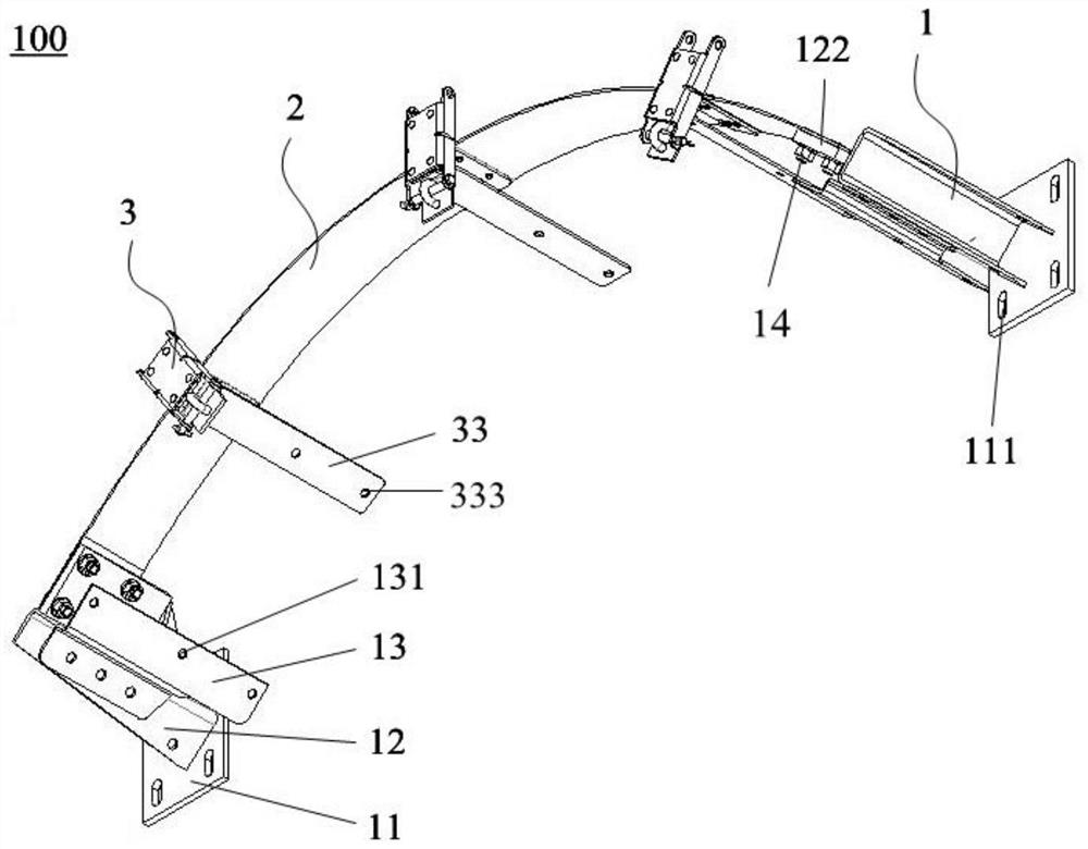
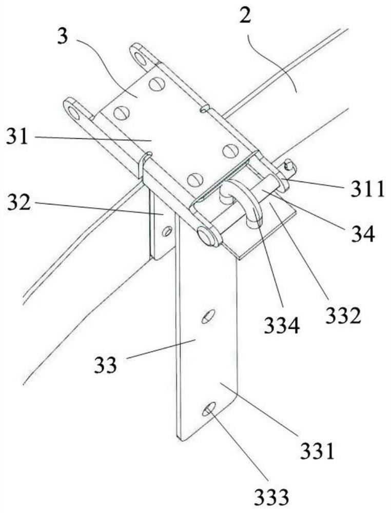
[0026] figure 1 and figure 2 The structures of the cabling frame 100 for the vehicle end of a rail vehicle according to the present invention are respectively shown from different viewing angles. Such as figure 1 As shown, the cable rack 100 includes a mounting base 1, an elastic plate 2, multiple clamp assemblies 3 and multiple engaging parts (not shown). There are two mounting bases 1 for being installed on the vehicle end. The elastic plate 2 is configured in an arc shape, and the two circumferential ends of the elastic plate 2 are installed on the two mounting bases 1 respectively. A plurality of wire clip assemblies 3 are distributed along the extension of the elastic board 1 and installed on the elastic board 2 at even intervals. A plurality of engaging parts can be fitly connected with the mounting base 1 and the wire clamp assembly 3, so that a plurality of engagements are respectively fo...


PUM


Abstract

The present invention provides a cable rack for the end of a rail vehicle, comprising: two mounting seats for mounting on the end of the vehicle; an arc-shaped elastic plate, and the circumferential ends of the elastic plate are respectively installed on the two ends of the elastic plate; On the mounting seat; a plurality of clamp assemblies evenly spaced and arranged on the elastic plate; Adaptive connection, so that a plurality of engaging parts are correspondingly formed between the engaging part and the mounting seat, and between the engaging part and the clamp assembly, and the cable harness is laid on the clamp and the wiring direction of the cable harness is along the extending direction of the elastic plate.

Description

technical field [0001] The invention belongs to the technical field of cable fixing at the vehicle end, and in particular relates to a cable rack used at the vehicle end of a rail vehicle. Background technique [0002] The cable rack is used to support the cable routing at the end of the rail vehicle to avoid problems such as electric leakage caused by cable wear and tear when the vehicle is moving. Due to the fact that there are many cables and electrical wires at the end of the rail vehicle, random placement is likely to cause damage, wear, etc., which will affect the service life of the cables and electrical pipelines. Therefore, the cable tray usually needs to meet the support requirements, and can meet the requirements of moving with the vehicle end and not interfering with the vehicle when the vehicle is moving. [0003] At present, the existing cable rack usually adopts a supporting rod provided on the vehicle connector, and the cables are hung on the supporting rod....

Claims


Application Information

Patent Timeline
Patent Type & Authority Patents(China)
IPC IPC(8): H02G3/32
CPCH02G3/32
Inventor 邓雄方陈斌安保明
Owner HUNAN LIANCHENG TRACK EQUIP CO LTD
Why Eureka
Try Eureka