Water-vapor separation device and cleaning equipment

A technology for water vapor separation and cleaning equipment, which is applied in the cleaning field and can solve problems such as increasing the cost of the suction fan, affecting the service life of the suction fan, and affecting heat dissipation

Pending Publication Date: 2021-08-31
WUXI NEWSTART CONTROLS TECH CO LTD
View PDF3 Cites 12 Cited by
  • Summary
  • Abstract
  • Description
  • Claims
  • Application Information

AI Technical Summary

Problems solved by technology

[0003] However, in the process of suction cleaning the ground and collecting garbage into the garbage collection area, since the liquid garbage on the ground will form a liquid flow (which can be referred to as water flow or water for short)...

Method used


Image

  • Water-vapor separation device and cleaning equipment
  • Water-vapor separation device and cleaning equipment
  • Water-vapor separation device and cleaning equipment

Examples


Embodiment 1

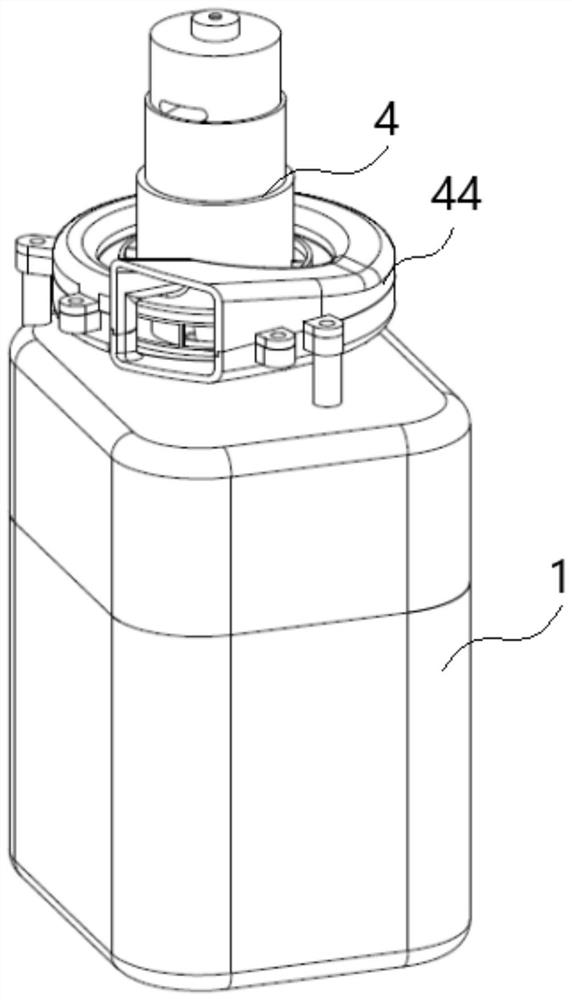
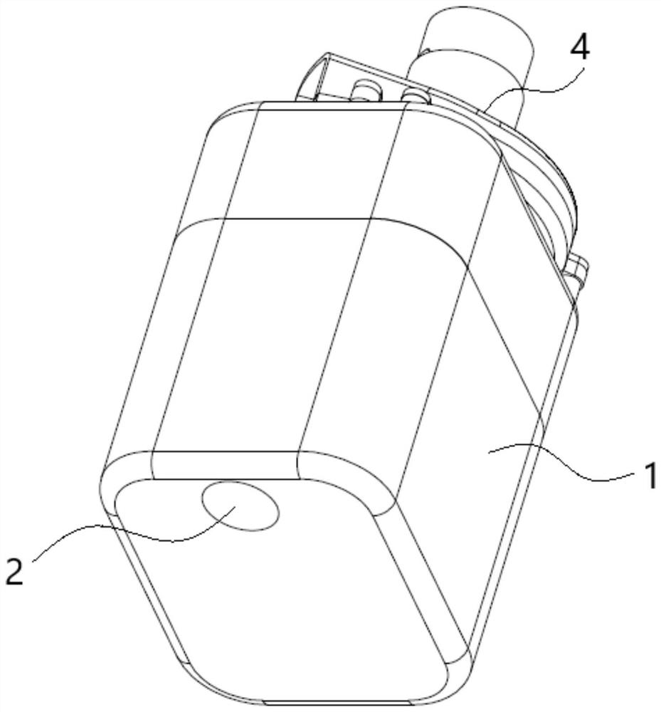
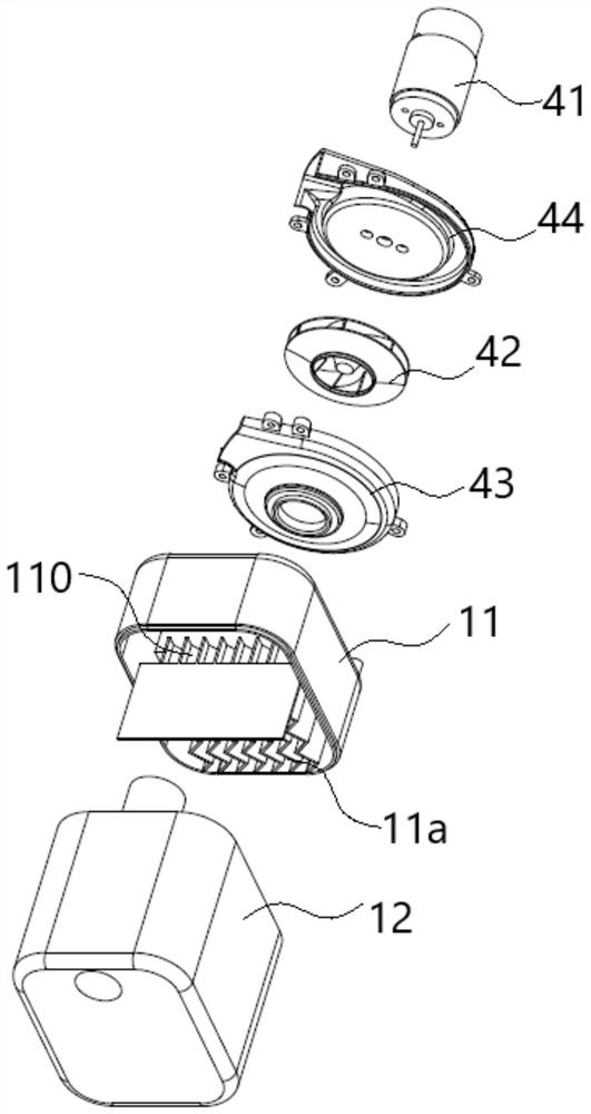
[0035] Example 1: see figure 1 , figure 2 , image 3 and Figure 4 A water vapor separation device 1 shown (in combination with Figure 5 shown), including the water vapor separation installation housing 13 respectively provided with the water vapor separation area 1a and the liquid collection area 12, the water vapor separation installation housing 13 (can use a cover plate type split installation structure, the figure has been shown, but not marked ) is installed and connected with the suction fan 4 as a whole; the water vapor separation area 1a includes a water vapor separation part 11 connected to the air flow inlet end 11b, the air flow outlet end 11c and the liquid outlet end 11a respectively, and the air flow inlet end 11b is connected to the suction channel 2 through the suction channel 2. The suction port 3 is communicated; the air flow outlet end 11c is communicated with the air inlet of the suction fan 4; the liquid collection area 12 is matched with the liquid ...

Embodiment 2

[0045] Embodiment 2: the remaining schemes of this embodiment 2 are the same as the above embodiment 1, the difference is that please refer to Image 6 , Figure 7 and Figure 8 In the shown water vapor separation device 1', in this embodiment 2, the water vapor separation part includes a flow isolation unit and an air flow centrifugal unit respectively installed inside the water vapor separation installation housing 13', wherein the pump connected to the air flow inlet port 11b The suction channel 2' uses a tangential air inlet 2a' to achieve primary centrifugal separation of the liquid in the airflow entering the water vapor separation zone 1a'; specifically, preferably, in this embodiment, the flow blocking unit includes a cylindrical flow blocking part 120, the air flow centrifugal unit includes a centrifugal impeller 130 (also referred to as a separation blade) installed and connected to the flow partition and a centrifugal cone 140 (also referred to as a sinking cone) i...

Embodiment 3

[0048] Embodiment 3: the remaining schemes of this embodiment 3 are the same as the above embodiment 2, the difference is that please refer to Figure 9 and Figure 10 In the shown water vapor separation device 1", in the present embodiment 3, the airflow centrifugal unit includes a curved surface centrifugal part 150, the airflow inlet end 11b (non-tangential air inlet structure) is located below the curved surface centrifugal part 150, and the airflow inlet end 11c is located The top of the curved surface centrifugal part 150; the water-vapor separation installation housing 13' (the rib shape that is beneficial to the water-vapor separation can be provided at its upper end part) and the middle part extends upwardly to the inner side of the inner passage housing 131 (from the liquid collection area 12' to the The water vapor separation zone 1a") forms the suction channel 2 (part of the channel section belonging to the suction channel) communicated with the air inlet port 11b,...


PUM


Abstract

The invention discloses a water-vapor separation device and cleaning equipment. The water-vapor separation device comprises a water-vapor separation mounting shell which is provided with a water-vapor separation area and a liquid collection area, wherein the water-vapor separation mounting shell is connected with a suction fan; the water-vapor separation area comprises a water-vapor separation part which is respectively connected with an airflow inlet end, an airflow outlet end and a liquid outlet end, and the airflow inlet end is communicated with a suction port through a suction channel; the airflow outlet end is communicated with an air inlet of the suction fan; and the liquid collection area is correspondingly matched with the liquid outlet end for collecting liquid. According to the invention, the liquid content of airflow entering the suction fan can be effectively avoided or greatly reduced, the service life of the suction fan is ensured, and negative effects on the heat dissipation performance of the suction fan are avoided.

Description

technical field [0001] The invention belongs to the field of cleaning technology, and specifically relates to a water vapor separation device, and also relates to cleaning equipment applied by the water vapor separation device. Background technique [0002] In order to achieve a good cleaning effect on the ground, it has been proposed to install a cleaning device with a suction function, which specifically includes a suction fan and a suction port that are communicated through a suction channel. Negative pressure adsorption effect, and then suction and transfer the garbage (including liquid garbage) on the ground to the garbage collection area of ​​the cleaning equipment. [0003] However, in the process of vacuuming and cleaning the ground and collecting the garbage into the garbage collection area, since the liquid garbage on the ground will form a liquid flow (referred to as water flow or moisture), the water flow will follow the airflow into the suction fan. , thereby a...

Claims


Application Information

Patent Timeline
IPC IPC(8): A47L11/40A47L11/30B01D53/26B01D53/24
CPCA47L11/302A47L11/4027B01D53/24B01D53/26
Inventor 周鹏李磊
Owner WUXI NEWSTART CONTROLS TECH CO LTD
Why Eureka
Try Eureka