Efficient full-automatic punching machine

A fully automatic, stamping machine technology, applied in the direction of feeding device, positioning device, storage device, etc., can solve the problems of low degree of automation, low work efficiency, unable to meet market needs, etc., to improve processing efficiency, improve positioning accuracy, The effect of preventing deformation

Active Publication Date: 2021-08-31
JIAXING MIQUE PNEUMATIC EQUIP
View PDF7 Cites 0 Cited by
  • Summary
  • Abstract
  • Description
  • Claims
  • Application Information

AI Technical Summary

Problems solved by technology

[0004]However, the automation of the above-mentioned stamping steps is low at present, and the work efficiency is low, which cannot meet the current increasing market demand

Method used


Image

  • Efficient full-automatic punching machine
  • Efficient full-automatic punching machine
  • Efficient full-automatic punching machine

Examples


Embodiment Construction

[0065] The following description serves to disclose the present invention to enable those skilled in the art to carry out the present invention. The preferred embodiments described below are only examples, and those skilled in the art can devise other obvious variations.

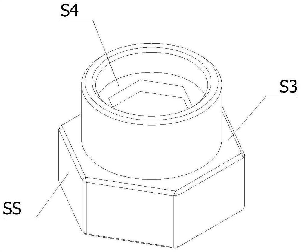
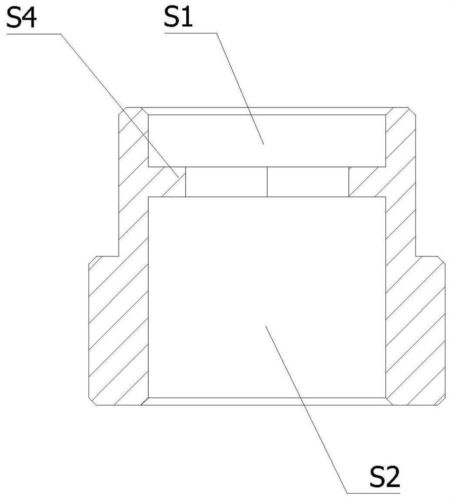
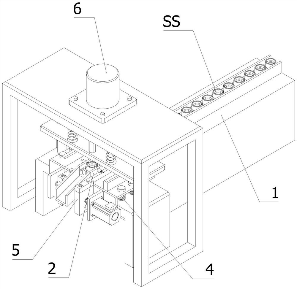
[0066] In order to solve the technical problem of how to efficiently complete the automatic stamping of the pipe connector SS to form the hexagonal through hole, such as Figure 1-11 As shown, the following technical solutions are provided:

[0067] A high-efficiency fully automatic stamping machine, including:

[0068] frame;

[0069] An automatic feeding device 1, the automatic feeding device 1 is installed on the frame, and the automatic feeding device 1 includes a vibrating plate and a feeding track 1a;

[0070] Also includes:

[0071] Movable track 2, movable track 2 can vertically lift and set, and movable track 2 is docked with the discharge end of feeding track 1a when it is located at the highes...


PUM


Abstract

The invention discloses an efficient full-automatic punching machine. The efficient full-automatic punching machine comprises a rack, an automatic feeding device, a movable rail, an abutting connection rod, a first elastic supporting assembly, an alignment assembly, a punching device, a limiting plate and a counting device. The movable rail is arranged in a manner of being capable of ascending and descending vertically, and when the movable rail is located at the highest position of movement of the movable rail, the movable rail is in butt joint with the discharging end of a feeding rail. The abutting connection rod and the rack are fixed, the abutting connection rod is located under the movable rail, the working direction of the abutting connection rod is vertically upward, and a first via hole allowing the abutting connection rod to penetrate through is formed in the bottom end of the movable rail. The first elastic supporting assembly is fixedly connected with the rack, and the working direction of the first elastic supporting assembly is vertically upward. The alignment assembly is provided with a pair of clamping jaws arranged oppositely and a driving device for driving the clamping jaws to move oppositely. The punching device is fixedly connected with the rack. The limiting plate is arranged on the inner side of a vertical plate of the movable rail in the horizontal direction . According to the technical scheme, the machining efficiency of pipeline connecting pieces is greatly improved.

Description

technical field [0001] The invention relates to the technical field of automatic processing of pipe connectors, in particular to a high-efficiency full-automatic stamping machine. Background technique [0002] Pipes are commonly used components in construction and industry. In order to facilitate production and uniform speed, multi-section pipes are often combined and connected through connectors to meet different actual needs. [0003] There is a pipe connector SS, the first end of which is a cylindrical structure, and the second end is a hexagonal prism integrally formed with the first end, the diameter of the second end is larger than the first end, and the connection between the second end and the first end A stepped surface S3 is formed on the outside, a first counterbore S1 is opened at the first end from the outer end toward the second end, and a second counterbore S2 is opened at the second end from the outer end towards the first end, the first counterbore A flange...

Claims


Application Information

Patent Timeline
Patent Type & Authority Applications(China)
IPC IPC(8): B21D28/28B21D28/04B21D43/02B21C51/00
CPCB21D28/28B21D28/04B21D43/02B21D43/006B21C51/00
Inventor 毛信强李刚胡志伟石尧峰
Owner JIAXING MIQUE PNEUMATIC EQUIP
Why Eureka
Try Eureka