Device for producing variable-diameter round bar material and machining method

A technology of variable diameter and driving device, which is applied in the direction of feeding device, metal processing equipment, metal processing machinery parts, etc., to achieve the effect of simple and fast operation, high precision and low labor intensity

Inactive Publication Date: 2021-08-31
辽阳奥鹏汽车零部件有限公司
View PDF13 Cites 0 Cited by
  • Summary
  • Abstract
  • Description
  • Claims
  • Application Information

AI Technical Summary

Problems solved by technology

[0004] Aiming at the deficiencies of the prior art, the present invention provides a device and processing method for producing variable-diameter round rod materials, which solves the actual problems that need to be solved in the existing background technology

Method used


Image

  • Device for producing variable-diameter round bar material and machining method

Examples


Embodiment 1

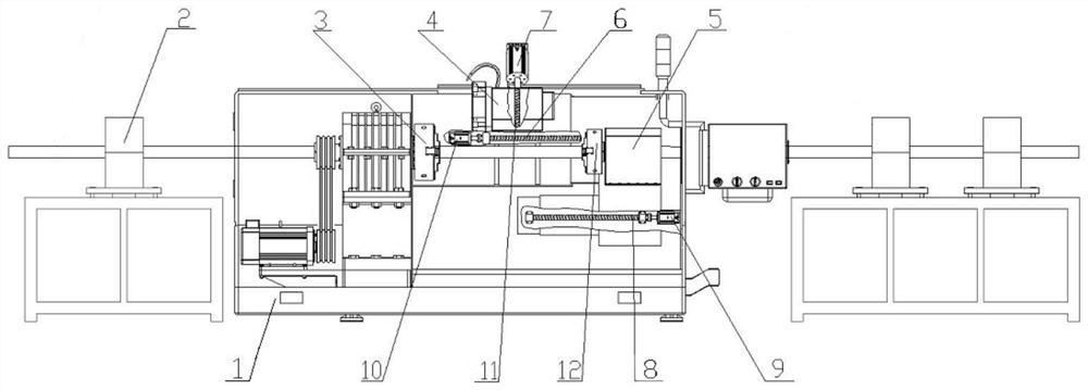
[0017] A device for producing variable-diameter round rod materials, including an equipment base 1 and fixed brackets 2 arranged on both sides of the equipment collective, and a front chuck 3 is arranged on the equipment base 1;

[0018] The right side of the equipment base 1 is provided with an automatic tailstock 5, and the bottom of the automatic tailstock 5 is provided with a driving device A for driving it to move;

[0019] The driving device A includes an automatic tailstock screw 8 that is rotatably connected to the bottom of the automatic tailstock 5, one end of the automatic tailstock screw 8 is rotatably connected to the equipment base 1, and the other end is matched with an automatic tailstock servo motor 9;

[0020] The top of the equipment base 1 is provided with a turning tool holder 4, and the bottom of the turning tool holder 4 is provided with a driving device B for driving it to move;

[0021] The driving device B includes a platen that is horizontally slidab...

Embodiment 2

[0025] A processing method for producing a variable-diameter round rod material, comprising the following steps:

[0026] Step 1. The first section of bar processing: first clamped by the front chuck 3, the bar is placed on the front chuck 3, the rear chuck 12 at the front end of the automatic tailstock 5 clamps the bar, and the automatic tailstock servo motor 9 drives The rotation of the automatic tailstock screw 8 drives the automatic tailstock 5 to return to the designated position, and the tool on the turning tool holder 4 turns the bar. The rotation of the seat screw 8 drives the automatic tailstock 5 to advance, and stops after feeding to the turning end of the bar. The rear chuck 12 executes the clamping command, forming a state where the front chuck 3 and the rear chuck 12 clamp the two ends of the bar;

[0027] Step 2. Processing of other sections of bar material: the program controls the turning tool holder 4 to repeatedly execute the work of setting the length and d...


PUM


Abstract

The invention discloses a machining method for producing a variable-diameter round bar material. The machining method comprises the following steps that 1, a first-section bar is machined, specifically, firstly, clamping is conducted through a front chuck, the bar is arranged on the front chuck in an abutting mode, the bar is clamped through a rear chuck at the front end of an automatic tailstock, a servo motor drives a lead screw C to rotate to drive the automatic tailstock to return to the designated position, the bar is turned through a tool on a tool turning base, after the first section is completed, the front chuck executes a loosening instruction, the automatic tailstock advances and stops after being fed to the turning end of the bar, the rear chuck executes a clamping instruction, and the state that the two ends of the bar are clamped through the front chuck and the rear chuck is formed; and 2, other sections of bars are machined, specifically, the tool turning base is controlled by a program to repeatedly execute the work of setting the length and the depth on the bar. The invention relates to the technical field of machines. According to a device and machining method for producing the variable-diameter round bar material, the production efficiency is high, the quality is stable, the precision is greatly improved, operation is easy and fast, and the labor intensity is relieved. The taper of any diameter can be obtained.

Description

technical field [0001] The invention relates to the field of mechanical technology, in particular to a device and a processing method for producing variable-diameter round rod materials. Background technique [0002] In the prior art, the processing method of round bar with variable diameter mainly adopts ordinary lathe processing, and the operator manually feeds and sets the tool for processing. [0003] For example, the invention patent application with application number 202110099469.5, although this patent can achieve uniform and stable feeding each time, it has low productivity, high cost, poor precision, poor coaxiality, and high labor intensity, which cannot meet the needs of modern production. Contents of the invention [0004] Aiming at the deficiencies of the prior art, the present invention provides a device and a processing method for producing variable-diameter round rod materials, which solve the actual problems that need to be solved in the prior art. [00...

Claims


Application Information

Patent Timeline
IPC IPC(8): B23B5/08B23B1/00B23B21/00B23Q5/40
CPCB23B5/08B23B1/00B23Q1/25B23Q5/40
Inventor 赵强庞润兴
Owner 辽阳奥鹏汽车零部件有限公司
Why Eureka
Try Eureka