
Tool clamp for automobile part machining

A technology of auto parts and clamping, which is applied in the direction of manufacturing tools, metal processing equipment, metal processing machinery parts, etc., can solve the problems of unfixable, fixed misalignment, low fixing efficiency, etc., and achieve the effect of ensuring the firmness of reinforcement

Active Publication Date: 2021-08-31
安徽瑞系自动化科技有限公司
View PDF8 Cites 1 Cited by
  • Summary
  • Abstract
  • Description
  • Claims
  • Application Information

AI Technical Summary

Problems solved by technology

The existing tooling and fixtures for the processing of auto parts cannot fully fix the tubular shape characteristics when processing and fixing the tubular parts, resulting in low fixing efficiency and a decline in the product qualification rate. It is time-consuming and labor-intensive to place the workpiece on the fixture, and it is also easy to cause workpiece fixation misalignment

Method used


Image

  • Tool clamp for automobile part machining
  • Tool clamp for automobile part machining
  • Tool clamp for automobile part machining

Examples


Embodiment 1

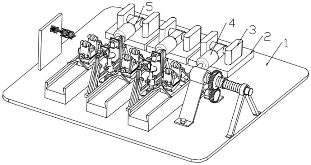
[0030] see figure 1 , in an embodiment of the present invention, the tooling fixture for processing auto parts includes:

[0031] A workbench 1, a fixed plate 2 is installed on the workbench 1, and a base 3 is installed on the fixed plate 2;

[0032] The connecting column 5 is rotatably connected between the bases 3, and the middle part of the connecting column 5 is equipped with a No. 1 telescopic output member 4;

[0033] The clamping and fixing assembly is installed on the workbench 1 and is used for multi-directional clamping and fixing of auto parts;

[0034] The conveying mechanism is installed on the workbench 1, and is used to convey the auto parts to the clamping and fixing assembly for fixing;

[0035] Wherein, the clamping and fixing assembly includes:

[0036] The No. 1 clamping mechanism is connected with the telescopic end of the No. 1 telescopic output member 4, and is used to realize the lateral fixation of auto parts;

[0037] The No. 2 clamping mechanism ...

Embodiment 2

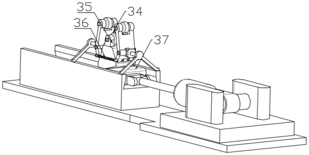
[0047] see figure 1 and Figure 5 , in the embodiment of the present invention, the No. 2 clamping mechanism includes:

[0048] The turret 15 is installed on the workbench 1;

[0049] The No. 2 telescopic output part 19 is located on the workbench 1 and is located between the turrets 15. The telescopic end of the No. 2 telescopic output part 19 is connected with a sliding rod 22, and one end of the sliding rod 22 is equipped with a limit plate. 23. The limit plate 23 is used to support the auto parts;

[0050] A sliding sleeve 21, the sliding sleeve is arranged on the sliding rod 22, and the sliding sleeve 21 is rotatably connected with a vertical rod 26;

[0051] The push rod 20 is connected with the vertical rod 26, and one end of the push rod 20 is fixedly equipped with a rotating rod 16, and the rotating rod 16 is connected with the turret 15;

[0052] Telescopic pump 18, the rotating rod 16 is connected to provide power for the rotation of the rotating rod 16;

[005...


PUM


Abstract

The invention relates to the field of automobile manufacturing, in particular to a tool clamp for automobile part machining. The tool clamp for automobile part machining comprises a workbench, a plurality of fixed plates are arranged on the upper side of the workbench, a plurality of bases are symmetrically arranged on the upper sides of the fixed plates, a connecting column is fixedly arranged between every two adjacent bases through a connecting rod, a first telescopic output piece is connected to the rear end of the connecting column, a first clamping mechanism is connected to the telescopic end of the first telescopic output piece, the first clamping mechanism comprises a fixed clamping plate, a sliding block is arranged on one side, away from the first telescopic output piece, of the fixed clamping plate, a plurality of sliding columns are further arranged on the upper side of the workbench, sliding groove capable of being in front-back sliding connection with sliding block in a matched mode is formed in the sliding columns, and a plurality of limiting frames are further symmetrically arranged on upper sides of sliding columns in a front-back mode. The tool clamp for automobile part machining is scientific in structure, fixing in all directions can be carried out on automobile parts, the fixing effect is good, and meanwhile time and labor are saved.

Description

technical field [0001] The invention relates to the field of automobile manufacturing, in particular to a tooling fixture for processing automobile parts. Background technique [0002] With the progress of society and the continuous development of science and technology, cars are becoming more and more common. In the production process of automobiles, many auto parts need to be used, and the shapes of auto parts are various. The existing tooling and fixtures for the processing of auto parts cannot fully fix the tubular shape characteristics when processing and fixing the tubular parts, resulting in low fixing efficiency and a decline in the product qualification rate. It is time-consuming and labor-intensive to place the workpiece on the fixture, and it is also easy to cause workpiece fixation misalignment. [0003] Therefore, in view of the above status quo, it is urgent to develop a tooling fixture for auto parts processing to overcome the deficiencies in current practic...

Claims


Application Information

Patent Timeline
IPC IPC(8): B23Q3/06
CPCB23Q3/06
Inventor 陈宏黄伟平
Owner 安徽瑞系自动化科技有限公司
Learn More