
Positioning assembly for steering wheel and steering wheel

A technology for positioning components and positioning parts, which is applied in steering control, steering mechanism, vehicle components, etc., and can solve problems such as driver discomfort, bad feel, and stuck positioning area

Pending Publication Date: 2021-08-31
AUTOLIV DEV AB
View PDF6 Cites 1 Cited by
  • Summary
  • Abstract
  • Description
  • Claims
  • Application Information

AI Technical Summary

Problems solved by technology

However, if the preload is designed too much, when the driver pushes the driver's airbag module to activate the horn function, the positioning area will get stuck
It's a bad touch and makes the driver uncomfortable
Therefore, more interference is usually not designed on the positioning area. This type of design will increase the risk of noise. The current problem is that it is difficult to strike a balance between noise and speaker feel.

Method used


Image

  • Positioning assembly for steering wheel and steering wheel
  • Positioning assembly for steering wheel and steering wheel
  • Positioning assembly for steering wheel and steering wheel

Examples


Embodiment 1

[0042] The positioning assembly for the steering wheel includes a first positioning part and a second positioning part, the first positioning part is inserted into the second positioning part, the first positioning part includes a first positioning part and a relief part, and the second positioning part includes a second positioning part Two positioning department;

[0043] Before pressing, the first positioning part is in close contact with the second positioning part and positioned;

[0044] After the first positioning part is pressed and rotated, the first positioning part is separated from the second positioning part, and the relief part is in clearance fit with the second positioning part.

[0045] Wherein, the first positioning member may be a positioning pin, or a raised insertion structure such as a positioning insert. The second positioning piece cooperates with the first positioning piece, and may be a positioning hole, or a positioning slot or other inserted struct...

Embodiment 2

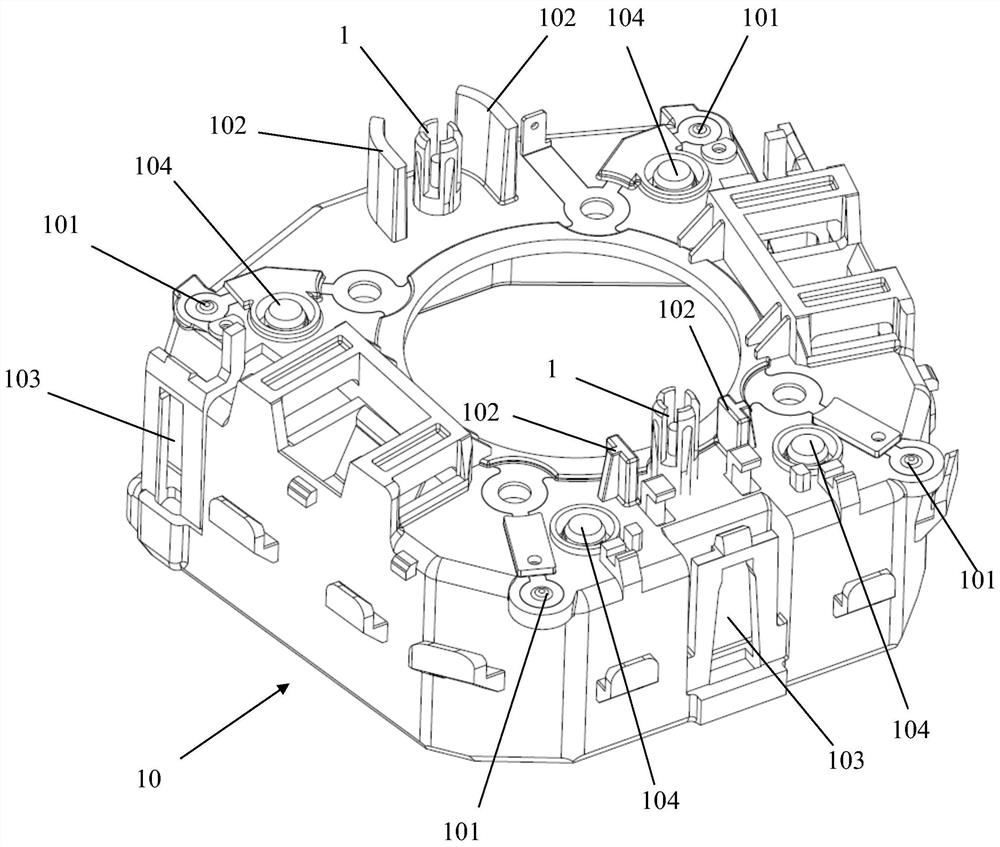
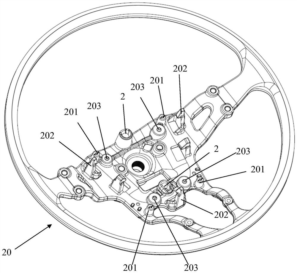
[0073] Such as Figure 1-2 As shown, the steering wheel includes an airbag housing 10 and a steering wheel frame 20, and also includes a positioning assembly. A first horn contact 101 is provided on the bottom surface, and a second horn contact 201 is provided on the top surface of the steering wheel frame 20 . When the first positioning member is pressed, the first horn contact 101 contacts the second horn contact 201 .

[0074] Specifically, as figure 1 As shown, the airbag housing 10 is a generally trapezoidal housing. figure 1 It is an inverted airbag housing 10 with two protruding positioning pins 1 arranged on its bottom surface, which are located on the front side and the rear side respectively.

[0075] The bottom surface of the airbag housing 10 is still provided with four first horn contacts 101, which are respectively located at the four corners.

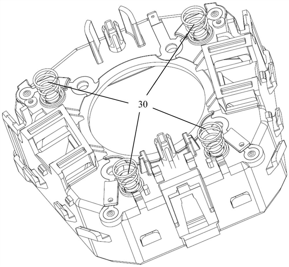
[0076] The bottom surface of the airbag housing 10 is also provided with four first spring mounting positions 104 . ...


PUM


Abstract

The invention discloses a positioning assembly for a steering wheel. The positioning assembly comprises a first positioning piece and a second positioning piece; the first positioning piece is inserted into the second positioning piece; the first positioning piece comprises a first positioning part and a receding part; the second positioning piece comprises a second positioning part; before pressing, the first positioning part and the second positioning part are in close contact and are positioned; after the first positioning piece is pressed to rotate, the first positioning part is separated from the second positioning part, and the receding part is in clearance fit with the second positioning part. The invention further discloses the steering wheel. Through the arrangement of the receding part, when a driver safety airbag module is pushed to activate a horn function, an airbag shell drives the first positioning piece to rotate, the receding part avoids interference between the positioning function of the airbag shell and a steering wheel framework, the hand feeling of a horn cannot be affected, and more pre-tightening force can be designed to avoid the noise problem.

Description

technical field [0001] The invention relates to the technical field of automobiles, in particular to a positioning assembly for a steering wheel and the steering wheel. Background technique [0002] In existing vehicles, the positioning area between the driver's airbag module and the steering wheel frame is usually designed with an interference fit pretightening force. However, if the preload is designed too much, when the driver pushes the driver's airbag module to activate the horn function, the positioning area will get stuck. It's a bad feel and can make the driver uncomfortable. Therefore, more interference is usually not designed on the positioning area. This type of design will increase the risk of noise. The current problem is that it is difficult to strike a balance between noise and speaker feel. [0003] Therefore, it is necessary to design a positioning assembly for a steering wheel and a steering wheel that reduce noise and have a better feel when pressing the...

Claims


Application Information

Patent Timeline
IPC IPC(8): B62D1/04
CPCB62D1/046
Inventor 桑瑞刚梁铭飞张一麟
Owner AUTOLIV DEV AB
Learn More