
Anchor bolt thermal shrinkage production line

A production line and heat-shrinking technology, applied in the direction of wrapping paper shrinkage, special packaging objects, tubular objects, etc., can solve the problems of low production efficiency, high labor intensity of workers, etc., to facilitate centralized transportation, reduce labor intensity and labor costs, The effect of facilitating overall packaging

Pending Publication Date: 2021-08-31
CSIC HAIWEI ZHENGZHOU HIGH TECH CO LTD +1
View PDF13 Cites 0 Cited by
  • Summary
  • Abstract
  • Description
  • Claims
  • Application Information

AI Technical Summary

Problems solved by technology

[0004] The purpose of the present invention is to provide an anchor bolt heat-shrinkable production line to solve the technical problems in the prior art that manual hand-held heat guns heat the heat-shrinkable tubes at both ends of the anchor bolt one by one, resulting in low production efficiency and high labor intensity for workers.

Method used


Image

  • Anchor bolt thermal shrinkage production line
  • Anchor bolt thermal shrinkage production line
  • Anchor bolt thermal shrinkage production line

Examples


specific Embodiment 1

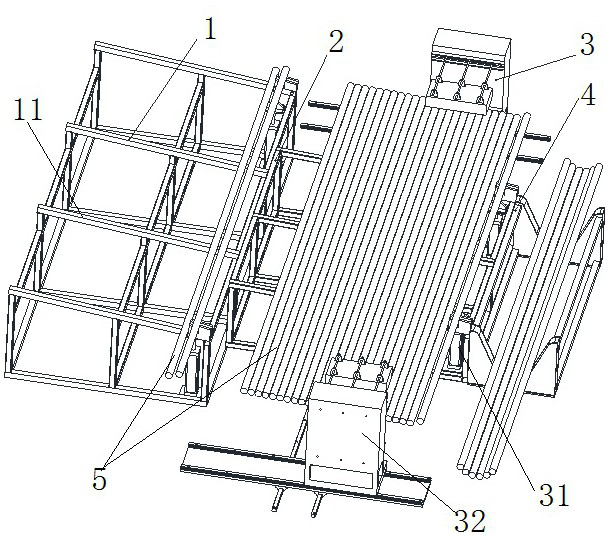
[0047] Such as Figure 1 to Figure 7 As shown, the anchor bolt heat shrink production line in this embodiment as a whole includes a feeding unit 1, a heat shrink unit 3 and a material receiving unit 4, and the feeding unit 1, heat shrink unit 3 and material receiving unit 4 are arranged in sequence along the front and rear directions The feeding unit 1 transfers the anchor bolts 5 one by one to the heat shrink unit 3 one by one. The heat shrink unit 3 is used to heat the heat shrink tubes 52 on both sides of the anchor bolt 5. After heating, the material receiving unit 4 receives the heat shrink to complete Anchor bolt 5.

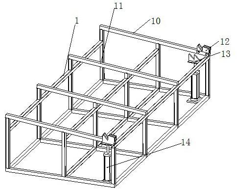
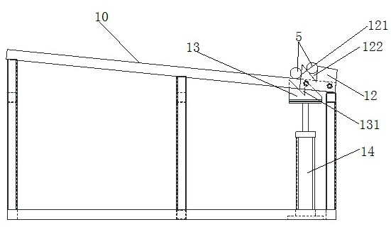
[0048] Specifically, the structure of the feeding unit 1 is as follows figure 1 , figure 2 and image 3 As shown, the loading unit 1 is used to transport the anchor bolt 5 to the heat shrinking platform 31 of the heat shrinking unit 3, and the loading unit 1 includes a loading platform, such as figure 2 As shown, the feeding platform is a frame struc...

specific Embodiment 2

[0063] The main difference between it and Embodiment 1 is that in Embodiment 1, the heaters on both sides move back and forth in the front and rear directions to realize the relative movement between the anchor bolt and the heater to complete shrinkage heating. In this embodiment, the heater is fixed in the front-to-back direction, and the heat-shrinkable support surface on the heat-shrink stand is arranged obliquely from front to back. The heating plate realizes heat shrinkage heating. It should be noted that this mode requires the unloading and lifting structure to continuously lift and transfer the anchor bolts to the receiving unit one by one. At this time, it is necessary to pay attention to the larger heating area of ​​the heater. to ensure efficient heating. In this way, the self-gravity of the anchor bolt is used to roll backward, eliminating the need for power drive.

[0064] Of course, in other embodiments, the heater can also be moved back and forth along the fron...

specific Embodiment 3

[0066] The main difference between it and Embodiment 1 is that in Embodiment 1, the heater adopts a planar heating structure formed by upper and lower heating plates to heat the heat-shrinkable tube. In this embodiment, the planar heating structure includes an upper heating plate and a lower reflecting plate, and the emitting plate realizes heat reflection heating, so that the upper heating plate and the lower reflecting plate cooperate to realize shrinkage heating.


PUM


Abstract

The invention relates to an anchor bolt thermal shrinkage production line. The anchor bolt thermal shrinkage production line comprises a feeding unit, a thermal shrinkage unit and a material receiving unit; the feeding unit is used for conveying an anchor bolt to the thermal shrinkage unit; the thermal shrinkage unit comprises a thermal shrinkage rack and a heater; the thermal shrinkage rack is provided with a thermal shrinkage supporting surface; the thermal shrinkage supporting surface is used for supporting and placing the anchor bolt to be heated; the heater is used for heating thermal shrinkage pipes at two ends of the anchor bolt to achieve thermal shrinkage fastening; and the material receiving unit is used for collecting the anchor bolt subjected to thermal shrinkage processing. In the anchor bolt thermal shrinkage production line provided by the invention, the anchor bolt is conveyed to the thermal shrinkage unit by the feeding unit, the anchor bolt is supported by the thermal shrinkage rack, and the thermal shrinkage pipes at the two ends of the anchor bolt are heated by the heater, so that thermal shrinkage fastening can be realized; and automatic operation is conveniently realized, manual operation is replaced, the labor intensity of workers and the labor cost are reduced, the anchor bolt thermal shrinkage processing efficiency is effectively improved, anchor bolts subjected to thermal shrinkage processing can be conveniently collected in a centralized mode, and centralized transportation and overall packaging of the anchor bolts are facilitated.

Description

technical field [0001] The invention relates to an anchor bolt heat shrink production line. Background technique [0002] Anchor bolts are large-scale threaded fasteners used in prestressed fan foundations, generally in the form of threads at both ends and polished rods in the middle. Such as Figure 7 As shown, in order to achieve the anti-corrosion effect, it is necessary to cover the polished rod part in the middle of the anchor bolt 5 with a PE tube 51, exposing the threaded sections 53 at both ends of the anchor bolt, and cover the two ends of the PE tube 51 with a heat shrinkable tube 52, and the heat shrinkable tube 52 To cover the PE pipe 51 and the anchor bolt at the same time, the heat-shrinkable pipe 52 will shrink after being heated, and pack the PE pipe and the anchor bolt together to play a good anti-corrosion effect. [0003] However, at present, the thermal shrinkage of anchor bolts is mainly completed one by one by operators holding heat guns, which has ext...

Claims


Application Information

Patent Timeline
IPC IPC(8): B65B53/02B65B35/10B65B61/28B65B19/34
CPCB65B53/02B65B35/10B65B61/28B65B19/34
Inventor 白洁都军民刘萍丁永春杨中桂王志敏刘禹赵梦涛靳逸飞王自强赵智垒
Owner CSIC HAIWEI ZHENGZHOU HIGH TECH CO LTD
Learn More