Steel ball grinding and cleaning equipment

A technology for cleaning equipment and steel balls, which is used in grinding/polishing equipment, spherical grinders, metal processing equipment, etc. It can solve the problems of inability to achieve functional coordination, increase the work intensity of workers, and complex grinding and cleaning equipment. Improve the efficiency of conversion, improve grinding efficiency, and improve the effect of processing efficiency

Active Publication Date: 2020-09-15
义乌市牵手电子商务有限公司
View PDF7 Cites 6 Cited by
  • Summary
  • Abstract
  • Description
  • Claims
  • Application Information

AI Technical Summary

Problems solved by technology

[0005] Aiming at the deficiencies of the prior art, the present invention provides a grinding and cleaning equipment for steel balls, which can realize the rotation of a power source, drive multiple mechanisms and devices to move to meet the cooperation required in the steel ball processing process, and improve the The efficiency of steel ball processing reduces the labor intensity, and at the same time reduces the cost of enterprise operation. It solves the problem that the steel ball grinding and cleaning equipment in the prior art is relatively complicated and the cost is relatively high. Equipment such as drums and drying boxes are combined into one processing line, and then the steel balls are polished and processed, which increases the operating cost of the enterprise and increases the work intensity of the workers. After grinding the steel balls, they need to be manually put into the The cleaning of the belt pulley reduces the processing efficiency of the steel balls and cannot achieve the problem of functional cooperation

Method used


Image

  • Steel ball grinding and cleaning equipment
  • Steel ball grinding and cleaning equipment
  • Steel ball grinding and cleaning equipment

Examples


Embodiment Construction

[0037] The following will clearly and completely describe the technical solutions in the embodiments of the present invention with reference to the accompanying drawings in the embodiments of the present invention. Obviously, the described embodiments are only some, not all, embodiments of the present invention. Based on the embodiments of the present invention, all other embodiments obtained by persons of ordinary skill in the art without making creative efforts belong to the protection scope of the present invention.

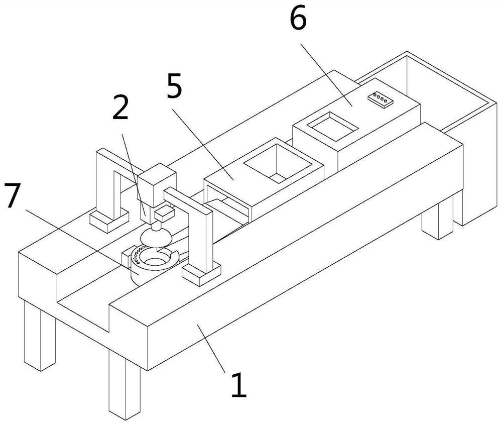
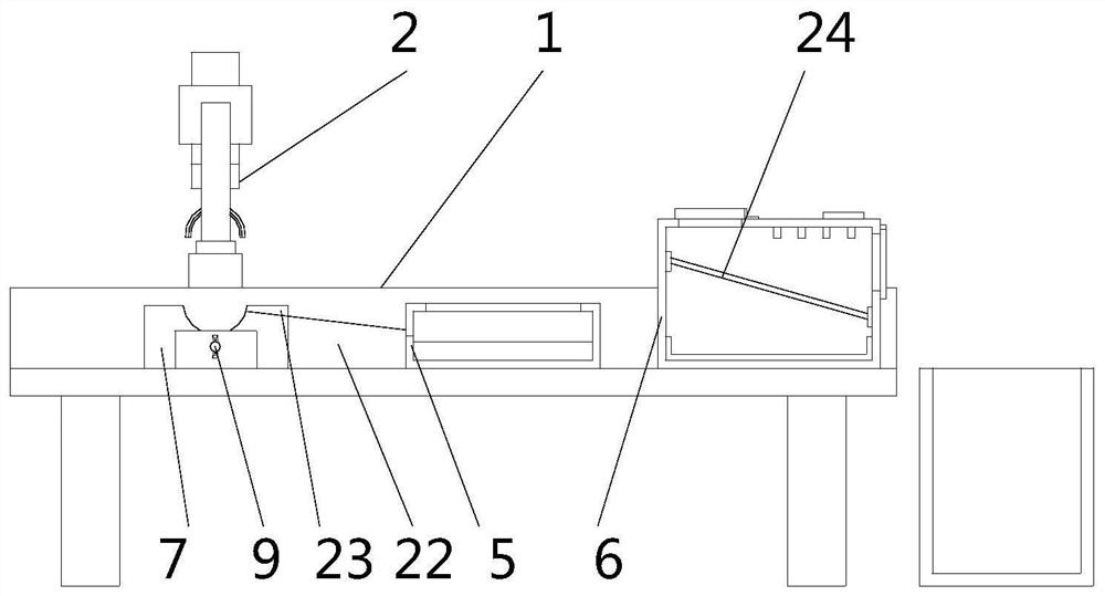
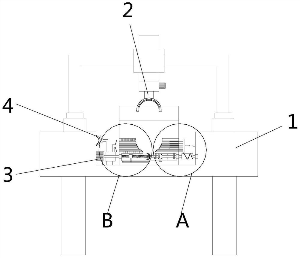
[0038] see Figure 1-11 , the present invention provides a technical solution: a steel ball grinding and cleaning equipment, including a workbench 1, a grinder 2, a servo motor 3, an air pump 4, a cleaning box 5, and a drying box 6. The bottom of the workbench 1 passes through four Two supporting legs are horizontally arranged on the ground, and the grinding machine 2 is fixedly installed on the top of the workbench 1 through a concave shape plate. The grindin...


PUM


Abstract

The invention relates to the technical field of metal machining, and discloses steel ball grinding and cleaning equipment. The steel ball grinding and cleaning equipment comprises a working table, a grinding machine, a servo motor, an air suction pump, a cleaning box and a drying box. A grinding table with a hollow cylinder is arranged in a rectangular groove in the front side of the working table. A limiting groove which is clamped with the bottom of a steel ball is formed in the top of the grinding table. Two groups of swinging mechanisms which are distributed up and down and are in continuous contact with the bottom of the steel ball are arranged in a grinding table cavity. According to the steel ball grinding and cleaning equipment, through the rotating of one power source, a pluralityof mechanisms and devices are driven to move to meet the requirements for cooperation needed in the steel ball machining process, the steel ball machining efficiency is improved, the labor intensityis reduced, and meanwhile, the operation cost of an enterprise is reduced; and by arranging the swinging mechanism, the grinding machine is used for performing full-angle grinding on the surface of the steel ball, the steel ball does not need to be manually turned or subjected to grinding angle changing, the grinding efficiency of the steel ball is improved, and the artificial working intensity isreduced.

Description

technical field [0001] The invention relates to the technical field of metal processing, in particular to a grinding and cleaning equipment for steel balls. Background technique [0002] Before the steel ball is painted, it needs to be polished, cleaned and dried. The purpose of grinding is to remove the dirt on the surface of the steel ball. Cleaning is to prevent the surface of the steel ball from being stained with polished metal debris. And powder, dried in order to evaporate the water on the surface of the steel ball after cleaning. [0003] The steel ball grinding and cleaning equipment in the prior art is relatively complicated and costly. It is often combined into a processing line through grinding machines, pulleys, cleaning drums, and drying boxes, and then the steel balls are polished and processed, which increases the cost of the enterprise. The cost of operation also increases the work intensity of the workers. After the steel balls are polished, they need to b...

Claims


Application Information

Patent Timeline
Patent Type & Authority Applications(China)
IPC IPC(8): B08B3/04B08B13/00F26B23/06B01D29/03B24B11/02B24B55/12
CPCB01D29/03B01D2029/033B08B3/04B08B13/00B24B11/02B24B55/12F26B23/06
Inventor 王伟
Owner 义乌市牵手电子商务有限公司
Why Eureka
Try Eureka