
Automatic cleaning device for belt conveyor of mixing plant

An automatic cleaning and belt conveyor technology, applied in the direction of cleaning devices, conveyors, conveyor objects, etc., can solve problems such as reducing labor intensity

Pending Publication Date: 2021-08-31
江苏双龙集团有限公司
View PDF6 Cites 0 Cited by
  • Summary
  • Abstract
  • Description
  • Claims
  • Application Information

AI Technical Summary

Problems solved by technology

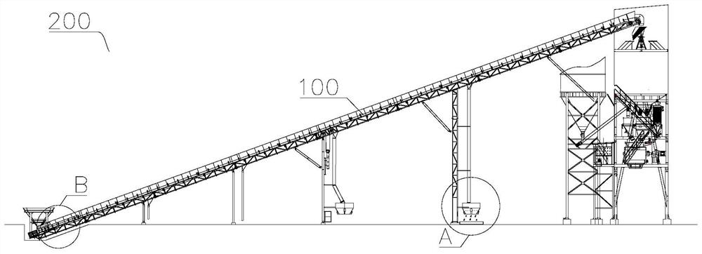
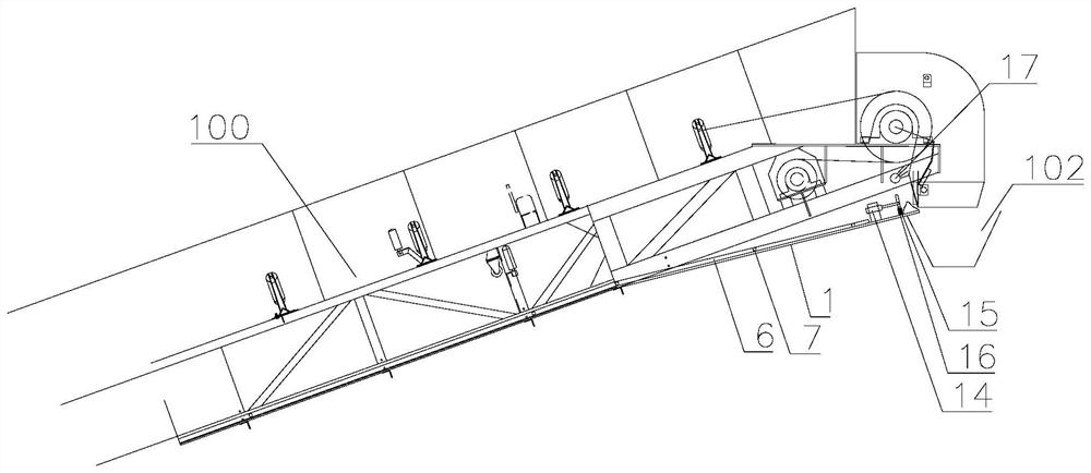
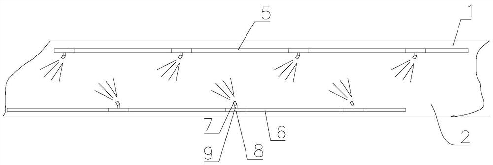
[0005] In order to solve the above problems, the object of the present invention is to provide an automatic cleaning device for the belt conveyor of the mixing station. The automatic cleaning device for the belt conveyor of the mixing station is equipped with a flushing device and a collecting device. The attached material drips or falls to the material receiving surface of the tray, and the washing component on the material receiving surface washes it, and the muddy water generated by the washing flows down the tray under the action of gravity and collects into the collecting hopper through the collecting pipe Inside, the waste in the collection bucket can be directly dropped into the bucket, and then transferred to the raw material shed by the bucket for reuse, which realizes automatic collection of waste, no need for manual cleaning and shipment, and reduces labor intensity and Untimely cleaning

Method used


Image

  • Automatic cleaning device for belt conveyor of mixing plant
  • Automatic cleaning device for belt conveyor of mixing plant
  • Automatic cleaning device for belt conveyor of mixing plant

Examples


Embodiment Construction

[0025] In order to explain the overall concept of the present invention more clearly, the following will be described in detail by way of examples in conjunction with the accompanying drawings.

[0026] In describing the present invention, it is to be understood that the terms "center", "upper", "lower", "front", "rear", "left", "right", "vertical", "horizontal", The orientation or positional relationship indicated by "top", "bottom", "inner", "outer", "axial", "radial" and "circumferential" are based on the orientation or positional relationship shown in the drawings, only It is for the convenience of describing the present invention and simplifying the description, but does not indicate or imply that the referred device or element must have a specific orientation, be constructed and operated in a specific orientation, and thus should not be construed as limiting the present invention.

[0027] In addition, the terms "first" and "second" are used for descriptive purposes only...


PUM


Abstract

The invention discloses an automatic cleaning device for a belt conveyor of a mixing plant. The automatic cleaning device comprises a flushing device and a collecting device, wherein the flushing device comprises a tray and a flushing component, the tray is arranged at the bottom of a truss of the belt conveyor in the length direction of the belt conveyor, the side, facing the belt conveyor, of the tray is a material receiving face, and the flushing component is arranged on the material receiving face and can flush the material receiving face; and the collecting device comprises a collecting pipe and a collecting hopper, the collecting hopper is arranged at the lower end of the tray, and muddy water flowing down from the material receiving face can enter the collecting hopper through the collecting pipe. According to the device, the flushing device and the collecting device are arranged, materials adhered to the surface of the belt fall to the material receiving face of the tray, the flushing component flushes the materials, the muddy water flows downwards along the tray and is collected into the collecting hopper through the collecting pipe, waste materials in the collecting hopper can be transferred to a raw material stacking shed through a bucket to be recycled, automatic waste material collection is achieved, manual cleaning, loading and transporting are not needed any more, the labor intensity of workers is relieved, and the situation that cleaning is not timely is also reduced.

Description

technical field [0001] The invention relates to the technical field of auxiliary equipment of a mixing station, in particular to an automatic cleaning device for a belt conveyor of a mixing station. Background technique [0002] During the production process of the mixing station, it is very easy to accumulate materials on the transmission rollers, redirecting rollers, lower rollers, etc., especially in the occasions where the loading and climbing belt conveyor has a large load, long running distance, and materials with high mud and water content. [0003] At present, most of them are cleaned manually with a shovel or temporarily washed with a hose. The accumulated material under the head drive roller is basically cleaned manually. The phenomenon that waste materials accumulate on the inner wall of the concrete will naturally collapse and slide into the bucket, and mixed with raw materials will seriously affect the quality of concrete. [0004] Since there is no collection ...

Claims


Application Information

Patent Timeline
IPC IPC(8): B65G45/22B65G45/12B65G45/26B65G15/00
CPCB65G45/22B65G45/12B65G45/26B65G15/00
Inventor 倪骏卜云兵史永红邹小童
Owner 江苏双龙集团有限公司
Learn More