
Thread trimming device and thread trimming method of embroidery machine

A technology for thread cutting and embroidery machines, which is applied in the field of thread trimming devices for embroidery machines. It can solve problems such as broken threads, off-threads, and messy thread ends, and achieve the effects of avoiding accidental cutting, improving the quality of embroidery, and avoiding waste residues

Pending Publication Date: 2021-08-31
浙江镨美科智能刺绣设备有限公司
View PDF1 Cites 5 Cited by
  • Summary
  • Abstract
  • Description
  • Claims
  • Application Information

AI Technical Summary

Problems solved by technology

[0005] Aiming at the problems existing in the prior art, the present invention proposes an embroidery machine thread trimming device and an embroidery machine thread trimming method, which can avoid messy thread ends and different thread lengths under the cloth surface, and solve the problem that the bottom thread breaks loose easily due to too loose stitches. The problem of off-thread and broken thread can also prevent the upper thread thread from being brought into the rotary hook to form new stitches, which will affect the quality of embroidery

Method used


Image

  • Thread trimming device and thread trimming method of embroidery machine
  • Thread trimming device and thread trimming method of embroidery machine
  • Thread trimming device and thread trimming method of embroidery machine

Examples


Embodiment approach

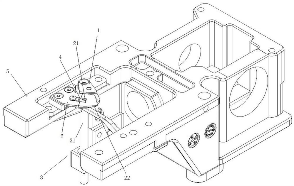
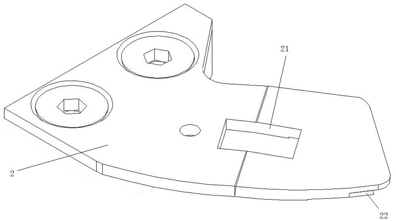
[0055] like image 3 , 5 Cutlery set the bottom portion of the thread, said fixed knife blade 2 towards a fixed knife blade 22 is provided. Fixed knife blade material is welded to the bottom of the fixed blade, by grinding the fixed knife blade is obtained. In one embodiment, the front end of the fixed cutter blade and the fixed portion of the thread scissors 22 is flush with the front end. In another embodiment, the predetermined portion of the front end of the thread scissors has an extended portion extending in the direction of the blade 1, so that the fixed knife blade 22 extending in the condensing portion. In the former embodiment, when the front edge and the knife blade intersects the fixed knife, scissors given once Spiraea taut the thread portion and the fixed knife blade, the cut will advance embroider, embroider or shearing. In the latter embodiment, since the presence of the extension portion, the extension portion blocking the advance Spiraea contact with the knife bla...


PUM


Abstract

The invention discloses a thread trimming device and thread trimming method of an embroidery machine, and belongs to the technical field of embroidery machines. The device comprises a movable cutter, a fixed cutter and a movable cutter driving mechanism; the movable cutter is mounted on a cutter bar of the movable cutter driving mechanism; a through hole is formed in the rear side of a fixed cutter edge of the fixed cutter; an embroidery thread retaining structure is arranged between the movable cutter and the fixed cutter and comprises an embroidery thread retaining body which at least partially acts on the upper surface of the movable cutter, and the acting part is located on the front side of a movable cutter edge; the front end of the embroidery thread retaining body extends in an upward trend to form the free end of the embroidery thread retaining structure, and the free end extends into the through hole; the embroidery thread retaining structure is used for binding the end of a bottom thread and / or an upper thread between the acting part and the movable cutter before thread trimming; and the movable cutter driving mechanism drives the movable cutter to move towards the fixed cutter, the movable cutter forks out the bottom thread and the upper thread to be cut during movement and continues to move towards the fixed cutter, and until the movable cutter coincides with the fixed cutter, the bottom thread and the upper thread are cut off. The method is realized based on the device. According to the invention, the thread end of the upper thread is prevented from being brought into a rotating shuttle to form a new stitch so as to affect the embroidery quality.

Description

Technical field [0001] The present invention belongs to the technical field of embroidery machines, and more particularly to an embroidery machine shear apparatus and an embroidery cutting method. Background technique [0002] At present, the embroidery machine industry, embroidery is completed, start embroidery another graphic unit, need to cut the wiring and bottom line below the layout, due to the numerous number of embroidered units, the cut line The line head left behind the rear needle is located below the place. Generally, the cutting machine cut lines After the needle embroidery adhesive, a flutter is passed through the display and separated into two stocks before and after, which has a coil to form a coil through the shot. Bottom line. During the formation of the coil, during the junction, since the wiring wire is not bonded, it is easy to make the embroidered line cannot be tightened. At this time, the wire below the layout is messy, the head head is short, and the qual...

Claims


Application Information

Patent Timeline
IPC IPC(8): D05C11/20
CPCD05C11/20
Inventor 陈天龙方狄永陈斌
Owner 浙江镨美科智能刺绣设备有限公司
Learn More