Check patentability & draft patents in minutes with Patsnap Eureka AI!

A building assembly type construction device

A construction device and assembly-type technology, which is applied in the direction of construction, building structure, and building material processing, can solve the problems of inconvenient use, low coordination, inability to reinforce and install operations, and facilitate support and erection operations. , easy to stretch the effect

Active Publication Date: 2022-08-02
安徽宸翰建设集团有限公司
View PDF6 Cites 0 Cited by
  • Summary
  • Abstract
  • Description
  • Claims
  • Application Information

AI Technical Summary

Problems solved by technology

[0006] Aiming at the deficiencies in the prior art, the present invention discloses a building assembly type construction device, which solves the problem of inability to flexibly select operations, inconvenient use, and inability to apply to subsequent reinforcement and installation operations and to the interior of buildings. work, resulting in a problem of low coordination

Method used


Image

  • A building assembly type construction device
  • A building assembly type construction device
  • A building assembly type construction device

Examples


Embodiment 1

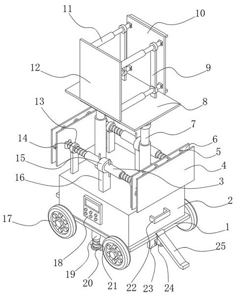
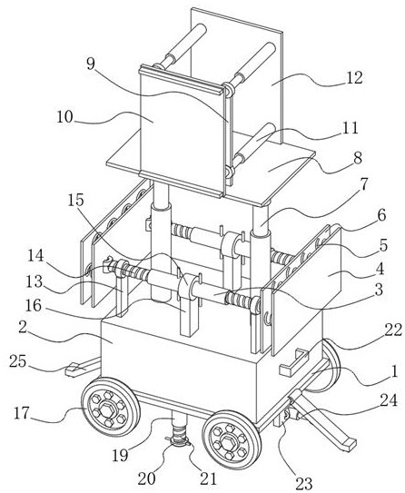
[0034] see Figure 1-6 As shown, the present invention provides a technical solution: a building assembly type construction device, comprising a base plate 1, the bottom of the base plate 1 is fixedly installed with two fixed thread cylinders 19, and the inside of the two fixed thread cylinders 19 are hinged with a second The threaded column 21, the bottom of the second threaded column 21 is fixedly installed with a ring plate 20, both sides of the bottom plate 1 are hinged with feet 25, and the bottom of the foot 25 away from the bottom of the bottom plate 1 is fixedly installed with a tooth claw 27, on both sides of the bottom of the bottom plate 1 The side plates 23 are fixedly installed, and the opposite sides of the side plates 23 are hinged with electric telescopic rods 24. The top of the bottom plate 1 is fixedly installed with the box 2, and the top of the box 2 is fixedly installed with two limit posts 16. A shaft seat 15 is fixedly installed at the top of each limit ...

Embodiment 2

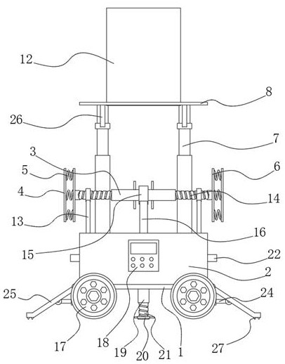
[0037] like Figure 1-6 As shown, on the basis of the first embodiment, the present invention provides a technical solution: the bottom of the ring plate 20 is fixedly installed with a cushion, the two sides of the ring plate 20 are fixedly installed with rotating columns, and the output end of the electric telescopic rod 24 Hinged on one side of the foot 25.

[0038] In this embodiment, when the operator rotates the rotating column to drive the ring plate 20 to rotate, the rotating force is applied to the hinged connection between the second threaded column 21 and the fixed threaded cylinder 19 downward, so that the cushion at the bottom of the ring plate 20 contacts the ground, increasing friction At the same time, the telescoping of the electric telescopic rod 24 makes the feet 25 support on the ground, which can cooperate with the soft pad to increase the friction force, so that the equipment can stand more stably and is easy to assemble.

Embodiment 3

[0040] like Figure 1-6 As shown, on the basis of Embodiment 1 and Embodiment 2, the present invention provides a technical solution: the top ends of the four movable struts 13 are all movably sleeved on the outside of the first threaded column 14, and the compression spring 5 is filled linearly. Evenly distributed on the opposite sides of the fixed plate 6 and the soft plate 4, a support plate 12 is fixedly installed on one side of the top of the top plate 8, and four hydraulic telescopic rods 11 are fixedly installed on one side of the support plate 12. The output end is hinged with the card plate 10, the outer side of the four hydraulic telescopic rods 11 is movably sleeved with a movable strut 9, the bottom of the movable strut 9 is fixedly installed on the top of the top plate 8, and one end of the two brackets 26 away from the top plate 8 is movable sleeve. Connected to the outside of the hydraulic telescopic column 7.

[0041] In this embodiment, the movable strut 13 p...


PUM


Abstract

The invention discloses a building-assembled construction method, comprising a base plate, two fixed thread cylinders are fixedly installed at the bottom of the base plate, second thread columns are hinged inside the two fixed thread cylinders, and the bottoms of the second thread cylinders are fixedly installed There is a ring plate, both sides of the bottom plate are hinged with supporting feet, the bottom of one end of the supporting feet away from the bottom plate is fixedly installed with claws, and both sides of the bottom of the bottom plate are fixedly installed with side plates. By setting the clamping plate, the position of the plate is relatively fixed, which is convenient for the operator to reinforce the device. At the same time, when the hydraulic telescopic column is stretched to the highest point, the height of the clamping plate is the same as that of the supporting plate. When the hydraulic telescopic rod retracts, the clamping plate is The top of the support plate is on the top of the inner cavity of the building, and it takes on the role of temporary support. This solution can make the construction method more convenient in the construction of the assembly, reduce the labor intensity of the operation, and is suitable for the construction of most assemblies, and the operation effect is good. .

Description

technical field [0001] The invention belongs to the technical field of prefabricated buildings, and in particular relates to a prefabricated construction method for buildings. Background technique [0002] With the development of modern industrial technology, building houses can be manufactured in batches like machine production, as long as the prefabricated building components are transported to the construction site for assembly, and prefabricated buildings began to attract people in the early 20th century. The interest of the building was finally realized in the 1960s. The United Kingdom, France, the Soviet Union and other countries first made attempts. Due to the fast construction speed and low production cost of prefabricated buildings, they were quickly promoted all over the world. Improvements have increased flexibility and diversity, so that prefabricated buildings can not only be built in batches, but also have rich styles. They are relatively advanced prefabricated...

Claims


Application Information

Patent Timeline
Patent Type & Authority Patents(China)
IPC IPC(8): E04G21/14E04G21/16
CPCE04G21/14E04G21/16E04G21/162
Inventor 管亮亮沈家玲方学娣金双琪
Owner 安徽宸翰建设集团有限公司
Features
  • R&D
  • Intellectual Property
  • Life Sciences
  • Materials
  • Tech Scout
  • Unparalleled Data Quality
  • Higher Quality Content
  • 60% Fewer Hallucinations
Learn More