Supercharge Your Innovation With Domain-Expert AI Agents!

Cabling device for cable processing

A cable and cabling technology, which is applied in the manufacture of cables/conductors, circuits, electrical components, etc., can solve the problems of increasing the difficulty and cost of operation for users, inconvenient for users to use, and unable to fix the clamping effect of cabling molds.

Active Publication Date: 2021-08-31
CRANE GRP OF HUNAN CABLE TECH
View PDF4 Cites 0 Cited by
  • Summary
  • Abstract
  • Description
  • Claims
  • Application Information

AI Technical Summary

Problems solved by technology

[0004] Aiming at the problems existing in the prior art, the present invention provides a cable forming device for cable processing, which has the advantages of clamping the cable forming mold and conveniently replacing the cable forming mold, and solves the problem that existing users need to process according to each batch. The operation of replacing the cable mould, frequent disassembly and installation, frequent use of threads and screws, and uneven force are likely to cause damage to the internal thread and slip wires, resulting in inability to fix and damage the cable mould. The clamping effect increases the difficulty and cost of the user's operation, which is not convenient for the user to use.

Method used


Image

  • Cabling device for cable processing
  • Cabling device for cable processing
  • Cabling device for cable processing

Examples


Embodiment Construction

[0023] In order to further understand the content, features and effects of the present invention, the following examples are given, and detailed descriptions are given below with reference to the accompanying drawings.

[0024] The structure of the present invention will be described in detail below in conjunction with the accompanying drawings.

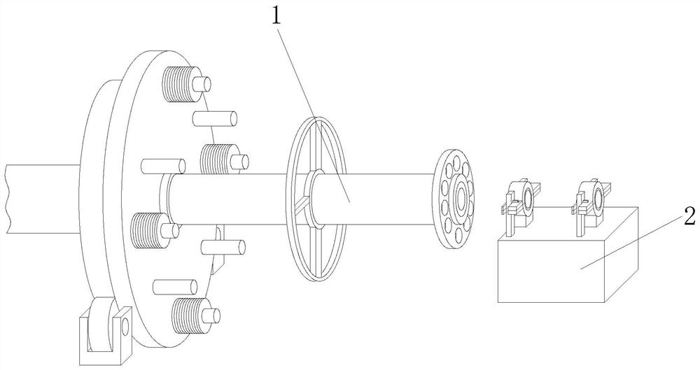
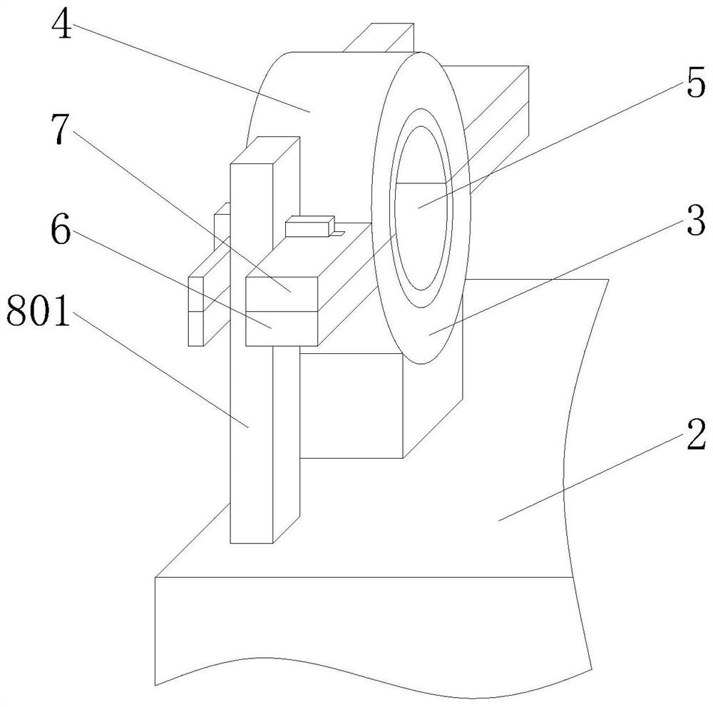
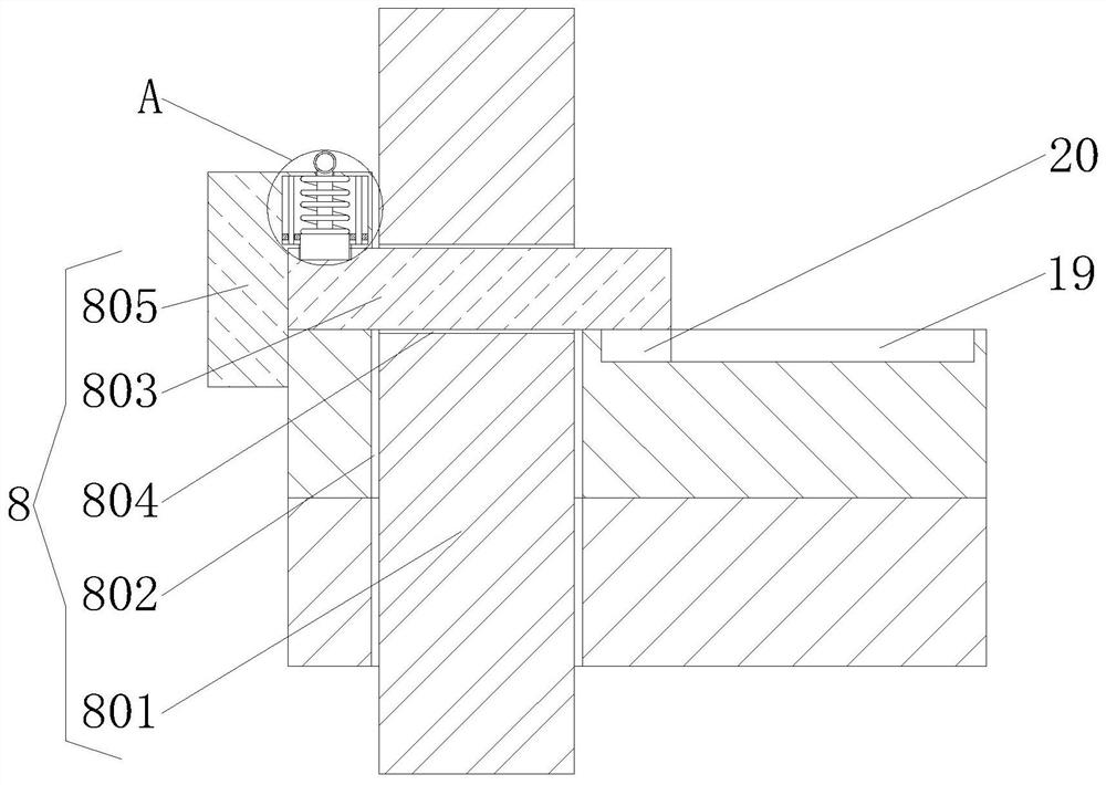
[0025] like Figure 1 to Figure 4 As shown, a cable forming device for cable processing provided by the embodiment of the present invention includes a lead wire device 1, an operation table 2 is arranged on the right side of the lead wire device 1, and two first splints 3 are fixedly connected to the top of the operation table 2, The top of the first clamping plate 3 is movably connected with a second clamping plate 4, and the opposite side of the first clamping plate 3 and the second clamping plate 4 is movably connected with a cable forming mold 5, and the front side and the rear side of the first clamping plate 3 are all fixedly c...


PUM


Abstract

The invention discloses a cabling device for cable processing, which comprises a lead device. The right side of the lead device is provided with an operation table, and the top of the operation table is fixedly connected with two first clamping plates. Through cooperative use of the first clamping plate, the second clamping plate and the supporting mechanism, a user can place a cabling mold between the first clamping plate and the second clamping plate, the supporting mechanism achieves a positioning effect after the first clamping plate and the second clamping plate are in contact, and the cabling mold is prevented from moving up and down; the problems that a user needs to replace a cabling mold according to different cabling numbers of cables in each batch at present, frequent disassembly and installation are caused, internal threads are damaged and slipped easily due to frequent use and uneven stress of the threads and screws, fixing cannot be achieved, the clamping effect on the cabling mold is poor, the operation difficulty and the operation cost of the user are increased, and the use of the user is not convenient can be solved, and the device is worthy of popularization.

Description

technical field [0001] The invention belongs to the technical field of cable processing, in particular to a cable forming device for cable processing. Background technique [0002] The cable forming machine is the main equipment for the production of power cables, plastic cables and rubber cables in the wire and cable factory. It is a complete set of equipment for connecting cables and armoring. It is redesigned by referring to the advanced cable-forming equipment at home and abroad and combining the actual situation of my country's wire and cable production. , steel belt head, meter counter, traction device, take-up line frame, electrical control and other parts. [0003] Cable forming is one of the steps in the centralized processing of lines in cable processing. The existing problems in the existing technology are: the user needs to replace the cable forming mold according to the number of cables in each batch, frequent disassembly and Installation, frequent use of thread...

Claims


Application Information

Patent Timeline
IPC IPC(8): H01B13/00
CPCH01B13/0036Y02P80/30
Inventor 汪振武
Owner CRANE GRP OF HUNAN CABLE TECH
Features
  • R&D
  • Intellectual Property
  • Life Sciences
  • Materials
  • Tech Scout
  • Unparalleled Data Quality
  • Higher Quality Content
  • 60% Fewer Hallucinations
Learn More