Power battery package leakage detection equipment

A power battery and leak detection technology, applied in the field of power batteries, can solve problems such as slow detection efficiency, high work difficulty, and high labor intensity, and achieve the effects of increasing maintenance costs, reducing labor intensity, and increasing work efficiency

Inactive Publication Date: 2021-08-31
李敬友
View PDF0 Cites 0 Cited by
  • Summary
  • Abstract
  • Description
  • Claims
  • Application Information

AI Technical Summary

Problems solved by technology

[0003] At present, most of the power batteries in the market rely on workers to manually detect the packaging leaks, which leads to high labor intensity and slow detection efficiency. Leak detection also relies on workers' work experience to judge, and the work is difficult. Therefore, a power battery packaging leak detection device is proposed to solve the above-mentioned problems

Method used


Image

  • Power battery package leakage detection equipment
  • Power battery package leakage detection equipment
  • Power battery package leakage detection equipment

Examples


Embodiment 1

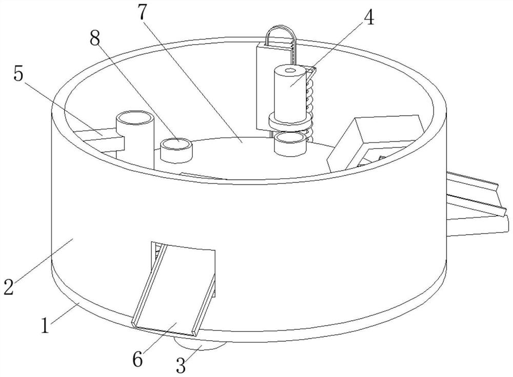
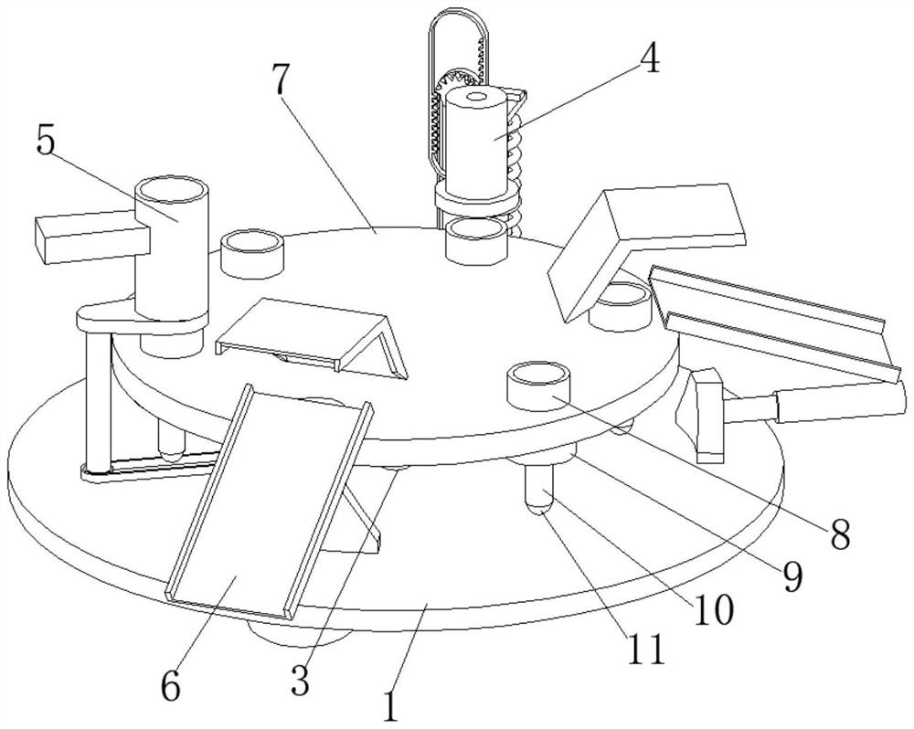
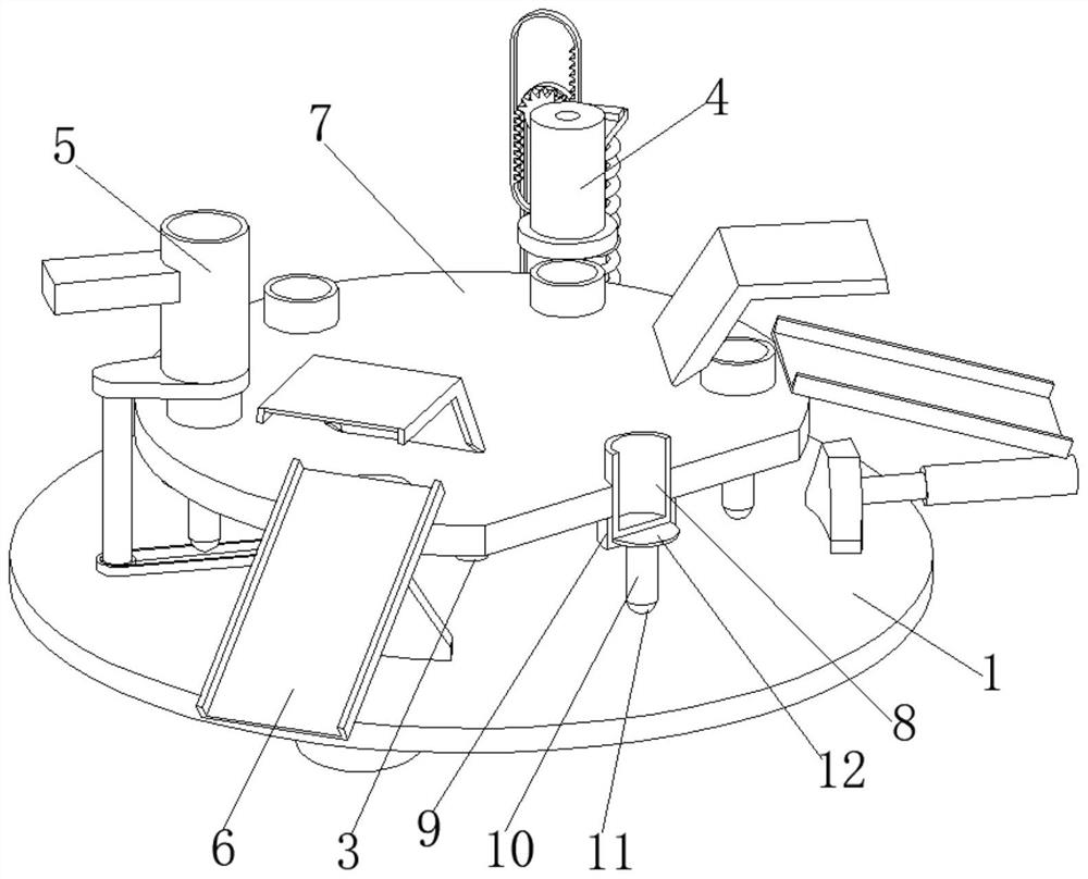
[0030] A power battery packaging leak detection equipment, such as Figure 1-Figure 6 As shown, including the mounting plate 1, the top of the mounting plate 1 is fixedly installed with a coaming plate 2, the bottom of the mounting plate 1 is provided with a transmission mechanism 3, and the inner wall of the coaming plate 2 is respectively provided with a detection mechanism 4, a feeding mechanism 5 and a discharge mechanism. mechanism 6, and the feeding mechanism 5 and the discharging mechanism 6 are respectively located on the left side and the front of the detection mechanism 4, the top of the transmission mechanism 3 is provided with a turntable 7, the inner wall of the turntable 7 is slidingly connected with a packaging shell 8, and the bottom of the turntable 7 A tray 9 is welded, the inner wall of the tray 9 is slidably connected with a support column 10, the bottom end of the support column 10 is rotatably connected with a ball 11, and the top of the support column 10 ...

Embodiment 2

[0044] Such as Figure 6-Figure 7 As shown, on the basis of Embodiment 1, in this embodiment, the surface of the No. 4 pulley 51 is connected to the surface of the double-layer pulley 37 through a belt, and the axis of the No. 4 pulley 51 is connected to the top of the mounting plate 1 in rotation. , the upper surface of the second cam 53 is in contact with the bottom end of the feed pipe 55 .

[0045] The feeding pipe 55 is located directly above the tray 9, so the packaging shell 8 can directly fall on the tray 9 to prevent it from falling off, and then cause it to not be loaded, causing the device to fail to work normally, and the practicability is greatly reduced.

[0046] The discharge mechanism 6 includes a No. 1 top board 61 and a No. 2 top board 62 . The surface of the No. 2 top board 62 is welded with an electric push rod 63 .

[0047] Through the discharging mechanism 6, the detected packaging shells 8 can be automatically discharged and classified, and workers are ...


PUM


Abstract

The invention relates to the technical field of power batteries, and discloses power battery package leakage detection equipment which comprises a mounting plate. A surrounding plate is fixedly mounted at the top of the mounting plate, a transmission mechanism is arranged at the bottom of the mounting plate, and a detection mechanism, a feeding mechanism and a discharging mechanism are arranged on the inner wall of the surrounding plate. The feeding mechanism and the discharging mechanism are located on the left side and the front portion of the detection mechanism correspondingly, a rotating disc is arranged at the top of the transmission mechanism, a packaging shell is slidably connected to the inner wall of the rotating disc, a tray is welded to the bottom of the rotating disc, supporting columns are slidably connected to the inner wall of the tray, and balls are rotatably connected to the bottom ends of the supporting columns. Through cooperative operation of the transmission mechanism and the detection mechanism, automatic leakage detection of the battery packaging shell can be realized, manual detection by workers is not needed, the labor intensity of the workers is reduced, the working efficiency is improved, and leakage detection can be carried out without experienced employees.

Description

technical field [0001] The invention relates to the technical field of power batteries, in particular to a leak detection device for power battery packaging. Background technique [0002] The power battery is the power supply that provides the power source for the tool. It mostly refers to the battery that provides power for electric vehicles, electric trains, electric bicycles, and golf carts. Lead-acid batteries, open tubular lead-acid batteries and lithium iron phosphate batteries. [0003] At present, most of the power batteries in the market rely on workers to manually detect the packaging leaks, which leads to high labor intensity and slow detection efficiency. Leak detection also relies on workers' work experience to judge, and the work is difficult. Therefore, a power battery packaging leak detection device is proposed to solve the above-mentioned problems. Contents of the invention [0004] The technical problem to be solved by the present invention is to provid...

Claims


Application Information

Patent Timeline
Patent Type & Authority Applications(China)
IPC IPC(8): H01M10/42
CPCH01M10/4228H01M10/4285Y02E60/10
Inventor 李敬友
Owner 李敬友
Why Eureka
Try Eureka