Head holder for neuro-interventional therapy
A technology of head immobilizer and nerve intervention, which is applied in the direction of stereotaxic surgical instruments, control of mechanical energy, electrical components, etc. It can solve the problems of increased force application area, strong local pressure, and uneven force application points on the patient's head.
- Summary
- Abstract
- Description
- Claims
- Application Information
AI Technical Summary
Problems solved by technology
Method used
Image
Examples
Embodiment 1
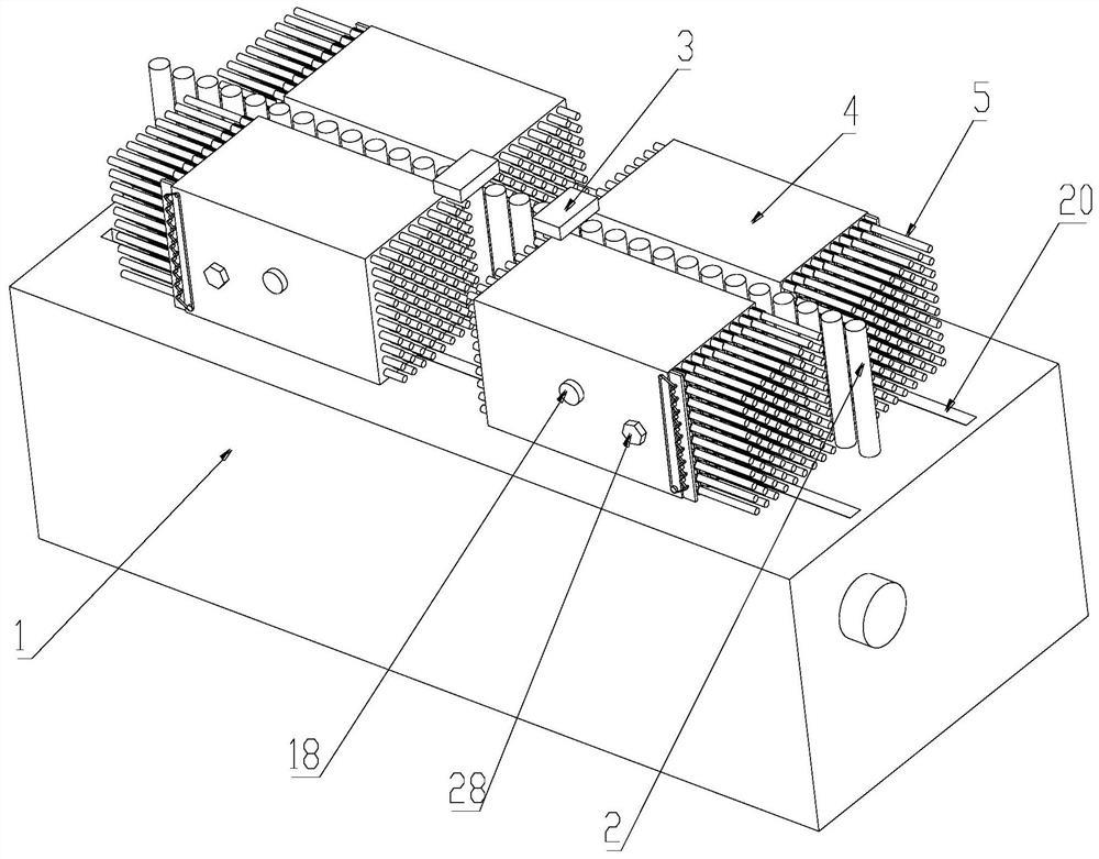
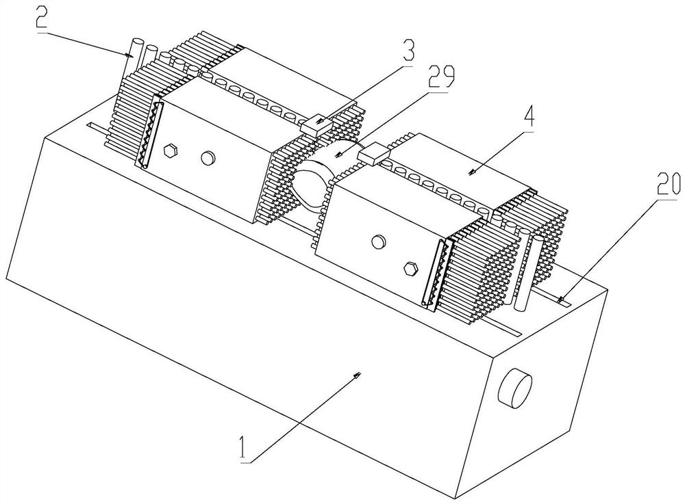
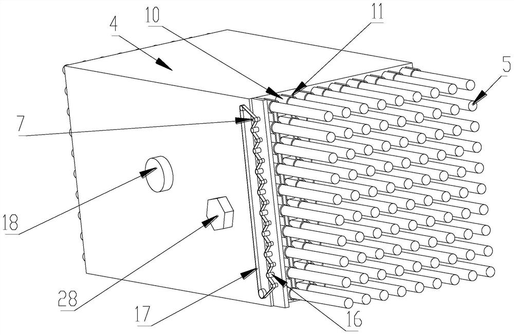
[0032] Such as Figure 1-9 As shown, a head immobilizer for neurointerventional therapy includes a base 1 on which a row of vertical elevating rods 2 are arranged from left to right, and the upper surface of the base 1 is placed on the elevating The two sides of the formation formed by the rods 2 are slidably connected with two uniformly stressed clips. The top of the lifting rod 2 is lower than the upper surface of the uniformly stressed clips. The base 1 is provided with a uniformly stressed clamp. Clamp control mechanism, the upper surface of the uniformly stressed clamp is provided with a sensor 3, and the distance between the adjacent surfaces of the two sensors 3 located on the same side of the elevating pole 2 is smaller than that located on the The distance between the adjacent surfaces of the two uniformly stressed clips on the same side of the elevating rod 2 formation, the uniformly stressed clip is provided with a brake automatic device, and the sensor 3 is electri...
Embodiment 2
[0035] Such as Figure 1-9 As shown, a head immobilizer for neurointerventional therapy includes a base 1 on which a row of vertical elevating rods 2 are arranged from left to right, and the upper surface of the base 1 is placed on the elevating The two sides of the formation formed by the rods 2 are slidably connected with two uniformly stressed clips. The top of the lifting rod 2 is lower than the upper surface of the uniformly stressed clips. The base 1 is provided with a uniformly stressed clamp. Clamp control mechanism, the upper surface of the uniformly stressed clamp is provided with a sensor 3, and the distance between the adjacent surfaces of the two sensors 3 located on the same side of the elevating pole 2 is smaller than that located on the The distance between the adjacent surfaces of the two uniformly stressed clips on the same side of the elevating rod 2 formation, the uniformly stressed clip is provided with a brake automatic device, and the sensor 3 is electri...
PUM
 Abstract
Description
Claims
Application Information
 - R&D
- Intellectual Property
- Life Sciences
- Materials
- Tech Scout
- Unparalleled Data Quality
- Higher Quality Content
- 60% Fewer Hallucinations
Browse by: Latest US Patents, China's latest patents, Technical Efficacy Thesaurus, Application Domain, Technology Topic, Popular Technical Reports.
© 2025 PatSnap. All rights reserved.Legal|Privacy policy|Modern Slavery Act Transparency Statement|Sitemap|About US| Contact US: help@patsnap.com


