Automatic cover mold grapnel device for high-end equipment manufacturing

A hook device and equipment technology, which is applied in the field of automatic hook device for cover molds for high-end equipment manufacturing, can solve the problems of broken cover molds, excessive physical strength, and consumption, and achieve the effect of reducing troubles

Inactive Publication Date: 2021-09-03
田小会
View PDF6 Cites 0 Cited by
  • Summary
  • Abstract
  • Description
  • Claims
  • Application Information

AI Technical Summary

Problems solved by technology

[0004] In order to overcome the disadvantages that manual handling requires a lot of physical strength and the cover mold is easily broken accidentally, the technical problem of the present invention is to provide an automatic cover mold for high-end equipment manufacturing that prevents damage to the cover mold. Grappling hook device

Method used


Image

  • Automatic cover mold grapnel device for high-end equipment manufacturing
  • Automatic cover mold grapnel device for high-end equipment manufacturing
  • Automatic cover mold grapnel device for high-end equipment manufacturing

Examples


Embodiment 1

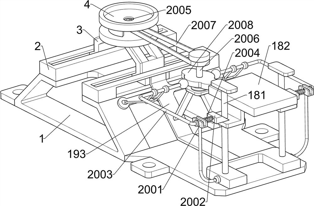
[0027] A cover mold automatic grabbing device for high-end equipment manufacturing, such as Figure 1-4 As shown, it includes base plate 1, first chute plate 2, sliding plate 3, disc 4, rotating cylinder 5, connecting block 6, first connecting plate 7, second chute plate 8, motor 9, first wire Rod 10, bevel gear set 11, second screw mandrel 12, first nut 13, first connecting rod 14, special-shaped plate 15, clamping assembly 16, rotating assembly 17 and placing assembly 18, the upper left and right sides of bottom plate 1 are all A first chute plate 2 is provided, a sliding plate 3 is provided slidingly between the first chute plates 2, a disc 4 is provided on the upper side of the sliding plate 3, and a rotating cylinder 5 is provided on the upper side of the disc 4 , the upper side of the rotating cylinder 5 is connected with the connecting block 6, the upper side of the connecting block 6 is connected with the first connecting plate 7, the lower left part of the first conne...

Embodiment 2

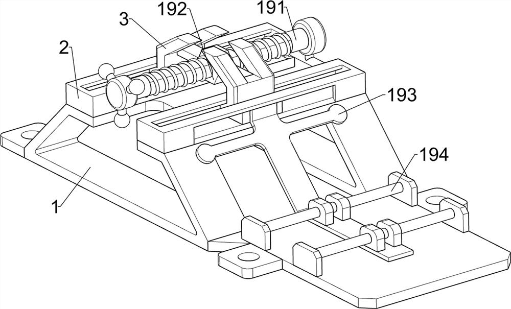
[0036] On the basis of Example 1, such as figure 1 , Figure 5 , Image 6 , Figure 7 and Figure 8 As shown, it also includes a front and rear moving assembly 19, and the front and rear moving assembly 19 includes a third screw rod 191, a third nut 192, a second support plate 193 and a fifth connecting rod 194, and the bottom plate 1 is rotatably connected with a third wire Rod 191, the sliding plate 3 is connected with a third nut 192, the third nut 192 is threaded with the third screw rod 191, the right side of the sliding plate 3 is connected with a second support plate 193, the second support plate 193 is connected with the fourth The connecting rods 181 are connected with each other, and the left and right sides of the right part of the base plate 1 are connected with fifth connecting rods 194 , and the fifth connecting rods 194 are connected with the second support plate 193 in a sliding manner.

[0037] When it is necessary to adjust the front and rear positions of...


PUM


Abstract

The invention relates to a grapnel device, in particular to an automatic cover mold grapnel device for high-end equipment manufacturing. The technical problem to be solved by the invention is to provide the automatic cover mold grapnel device for high-end equipment manufacturing, which can prevent a cover mold from being damaged. The automatic cover mold grapnel device for high-end equipment manufacturing comprises a bottom plate, first sliding groove plates, a sliding plate, a disc, a rotating cylinder, a connecting block, a first connecting plate, a second sliding groove plate, a motor, a first lead screw, a bevel gear set, a second lead screw, a first nut, a first connecting rod, a special-shaped plate, a clamping assembly, a rotating assembly and a placing assembly, wherein the first sliding groove plates are arranged on the two sides of the bottom plate correspondingly, and the sliding plate is arranged between the first sliding groove plates in a sliding mode; the disc is arranged on the sliding plate; and the rotating cylinder is rotationally arranged on the disc. The automatic cover mold grapnel device is provided with a front-back moving assembly, so that the front-back positions of the clamping assembly and the placing assembly can be integrally adjusted, and then the front-back positions of a grapnel are adjusted.

Description

technical field [0001] The invention relates to a grapple device, in particular to an automatic grapple device for a cover mold used in high-end equipment manufacturing. Background technique [0002] The cover molds for high-end equipment manufacturing need to be moved. Generally, the cover molds for high-end equipment manufacturing are moved manually. It is heavy, so it takes a lot of physical strength to carry it manually, and it is easy to accidentally break the cover mold when carrying it manually. [0003] Therefore need to design a kind of high-end equipment manufacture that prevents cover mold from being damaged and cover mold automatic grapple device. Contents of the invention [0004] In order to overcome the disadvantages that manual handling requires a lot of physical strength and the cover mold is easily broken accidentally, the technical problem of the present invention is to provide an automatic cover mold for high-end equipment manufacturing that prevents d...

Claims


Application Information

Patent Timeline
Patent Type & Authority Applications(China)
IPC IPC(8): B21D43/10B21D43/20
CPCB21D43/105B21D43/20
Inventor 田小会
Owner 田小会
Why Eureka
Try Eureka