Material coiling conveying mechanism for wood strip trimming

A conveying mechanism and coiling technology, applied in unloading equipment, wood processing appliances, circular saws, etc., can solve the problems of long time, complicated operation, affecting the efficiency of trimming of wood strips, etc., and achieve convenient operation, convenient replacement and location. Adjustment, convenient loading and unloading effect

Active Publication Date: 2019-05-14
JIAXING DAMING INDAL
View PDF10 Cites 0 Cited by
  • Summary
  • Abstract
  • Description
  • Claims
  • Application Information

AI Technical Summary

Problems solved by technology

[0007] Existing devices for trimming wood strips all include two cutting knives with a certain distance, through which the two sides of the strips are trimmed at one time, and in the process of trimming, the strips need to be moved, The trimming can only be done with the cutter. The existing wooden strips are moved manually, but most of them are transported by conveying devices. Most of the existing conveying devices use chains or belts for conveying, and the wooden strips need to be fixed. On the conveying device, this can ensure that there will be no deviation during edge trimming. However, in this way, the loading and unloading operations are complicated and time-consuming, which affects the efficiency of the entire wood strip trimming

Method used


Image

  • Material coiling conveying mechanism for wood strip trimming
  • Material coiling conveying mechanism for wood strip trimming
  • Material coiling conveying mechanism for wood strip trimming

Examples


Embodiment Construction

[0035] In order to enable those skilled in the art to better understand the technical solution of the present invention, the present invention will be described in detail below in conjunction with the accompanying drawings. The description in this part is only exemplary and explanatory, and should not have any limiting effect on the protection scope of the present invention. .

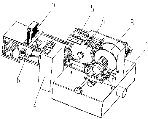
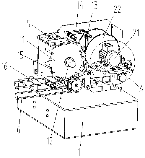
[0036] Such as Figure 1-Figure 6 As shown, the specific structure of the present invention is: a coil conveying mechanism for wood strip trimming, which includes a frame 1 and a power distribution control box 2, a coil device 4 is arranged on the frame 1 and is located at Its right side and the trimming device 3 that cooperates with it, described coiling device 4 comprises the coiling wheel 11 that is arranged on frame 1 and vertically places, and the coiling shaft 12 of described coiling wheel 11 is connected to coil The material output shaft 10, and the coiling wheel 11 rotates counterclockwise, th...


PUM


Abstract

The invention relates to a material coiling conveying mechanism for wood strip trimming. The material coiling conveying mechanism for wood strip trimming comprises a machine frame and a power distribution control box. A material coiling device and a trimming device are arranged on the machine frame. The material coiling device comprises a material coiling wheel arranged vertically on the machine frame, a material coiling shaft of the material coiling wheel is connected to material coiling output shaft, and the material coiling wheel rotates counterclockwise.A material discharging frame is arranged under the material coiling wheel, and installation notches are evenly formed in the material coiling wheel. Material pressing seats matched with wood bars are installed on the installation notches, a material pressing belt matched with the material coiling wheel is arranged on the right side of the material coiling wheel, the lower end of the material pressing belt is located under the material discharging frame, and the upper end of the material pressing belt is located above at the middle and right part of the material coiling wheel. According to the material coiling conveying mechanismfor wood strip trimming, the rotation of the wood bars around the material coiling wheel is realized by using the uniformly arranged material pressing seat on the material coiling wheel and the material pressing belt matched with the right side of the material coiling wheel, then the trimming of the wood bars is realized through a trimming cutter arranged on the right side of the material coilingwheel, a product is not required to be fixed to the material coiling wheel, feeding and discharging are greatly facilitated, and the efficiency of the whole trimming is improved.

Description

[0001] Original application number: 2016112203824 [0002] Applicant of the original case: Dongguan Ronggong Automation Technology Co., Ltd. [0003] Date of original filing: December 26, 2016 [0004] The name of the original application: a portable wood strip trimming machine. technical field [0005] The invention relates to the field of wood processing equipment, in particular to a coil conveying mechanism for trimming wood strips. Background technique [0006] In the wood processing process, it is often necessary to process wood into strips, and most of the strips need to be trimmed, so a strip trimming device is needed. [0007] Existing devices for trimming wood strips all include two cutting knives with a certain distance, through which the two sides of the strips are trimmed at one time, and in the process of trimming, the strips need to be moved, The trimming can only be done with the cutter. The existing wooden strips are moved manually, but most of them are tr...

Claims


Application Information

Patent Timeline
Patent Type & Authority Applications(China)
IPC IPC(8): B27B5/04B27B5/29B27B25/00B27B31/08B27B31/00B27B27/00
CPCB27B5/04B27B5/29B27B25/00B27B27/00B27B31/00B27B31/08
Inventor 黄红梅
Owner JIAXING DAMING INDAL
Why Eureka
Try Eureka