Auxiliary fixing device for pipe fitting cutting
A technology for fixing devices and pipe fittings, used in auxiliary devices, welding/cutting auxiliary equipment, auxiliary welding equipment, etc., can solve the problems of limited diameter range of pipe fittings, inability to meet the cutting needs of different pipe fittings, etc., and achieve the effect of increasing friction.
- Summary
- Abstract
- Description
- Claims
- Application Information
AI Technical Summary
Problems solved by technology
Method used
Image

Examples
specific Embodiment approach 1
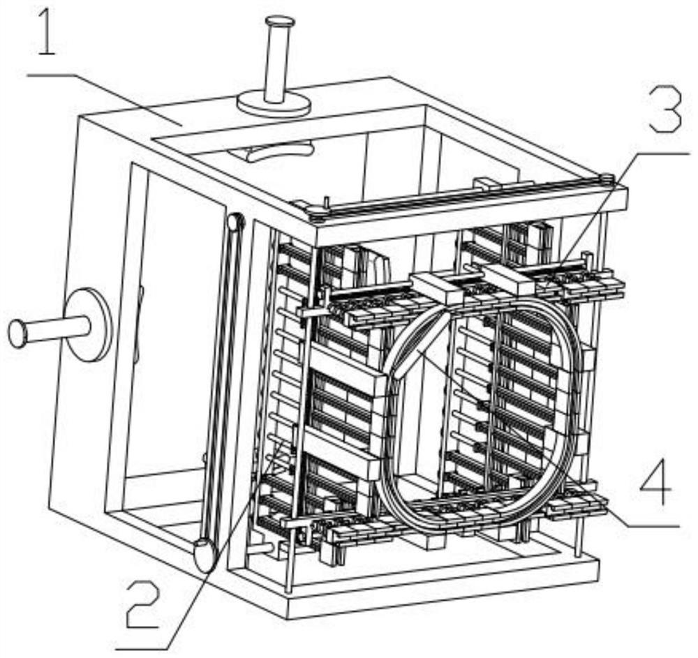
[0038] Combine below Figure 1-18 Describe this embodiment, a pipe cutting auxiliary fixing device, including a clamping mechanism 1, an expanded first mechanism 2, an expanded second mechanism 3 and an auxiliary track mechanism 4, the expanded first mechanism 2 is threaded with the clamping mechanism 1 Connection, the clamping mechanism 1 is threaded with the expansion second mechanism 3, the expansion second mechanism 3 is threaded with the auxiliary track mechanism 4, the auxiliary track mechanism 4 is threaded with the expansion first mechanism 2, and the auxiliary track mechanism 4 is slidably installed on the expansion first In the groove provided on the first mechanism 2, the auxiliary track mechanism 4 is slidably installed in the groove provided on the expanded second mechanism 3.
specific Embodiment approach 2
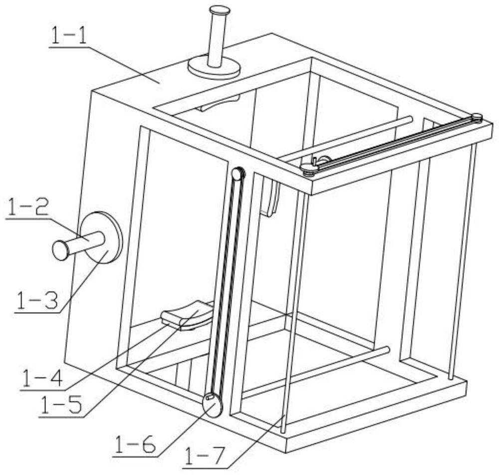
[0040] Combine below Figure 1-18 This embodiment will be described. This embodiment will further explain the first embodiment. The clamping mechanism 1 includes a clamping frame 1-1, a clamping threaded rod 1-2, an internal thread ring 1-3, and a supporting plate 1- 4. Rubber pad 1-5, adjustment component one 1-6, adjustment component two 1-7, internal thread ring 1-3 is rotatably installed in the groove set on the clamping frame 1-1, and clamps the threaded rod 1 -2 is threadedly connected with the internal thread ring 1-3, the supporting plate 1-4 is rotatably installed in the groove provided on the clamping threaded rod 1-2, and the supporting plate 1-4 is fixedly equipped with a rubber pad 1-5, Adjusting component 1-6 is rotatably installed in the groove provided on the clamping frame 1-1, and adjusting component 2 1-7 is rotatably installed in the groove provided on the clamping frame 1-1;
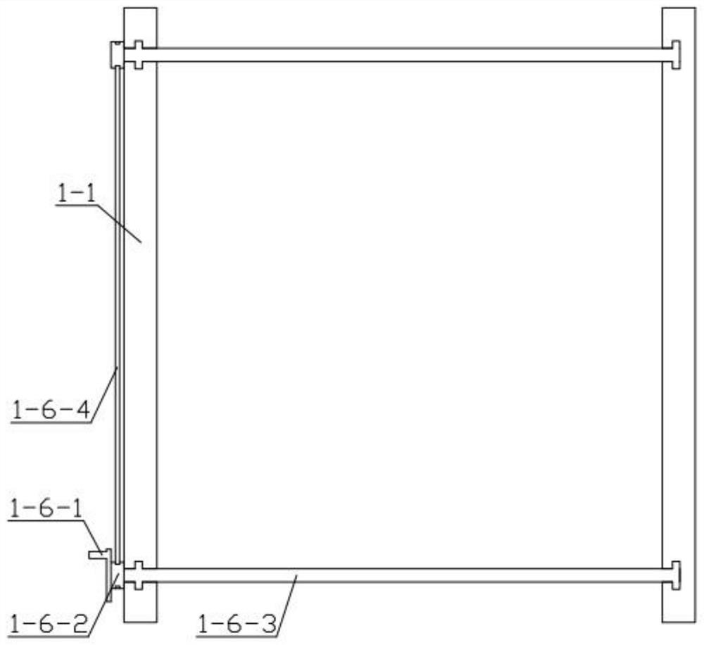
[0041] Adjustment assembly 1-6 includes hand plate 1-6-1, sprocket 1-6-2, long ...
specific Embodiment approach 3
[0044] Combine below Figure 1-18 Describe this embodiment, this embodiment will further explain the second embodiment, the first expansion mechanism 2 includes a side frame 2-1, an adjustment threaded rod 2-2, a sliding arm 2-3, and a short-circuit track plate 1 2-4, track batten one 2-5, track batten two 2-6, side frame one 2-1 is threadedly connected with long two-way threaded rod one 1-6-3, and side frame one 2-1 is fixedly installed with Track slat 1 2-5, side frame 1 2-1 is fixedly installed with track slat 2 2-6, and the adjustment threaded rod 2-2 is rotatably installed in the groove provided on side frame 1 2-1, and the adjustment thread The rod 2-2 is threadedly connected with the sliding arm 2-3, and the sliding arm 2-3 is fixedly installed with a short-circuit track plate 1 2-4, and the sliding arm 2-3 is slidably installed on the track slat 2-5 and the track slat 2. In the clamping groove formed by 2-6.
PUM
 Abstract
Description
Claims
Application Information
 - R&D
- Intellectual Property
- Life Sciences
- Materials
- Tech Scout
- Unparalleled Data Quality
- Higher Quality Content
- 60% Fewer Hallucinations
Browse by: Latest US Patents, China's latest patents, Technical Efficacy Thesaurus, Application Domain, Technology Topic, Popular Technical Reports.
© 2025 PatSnap. All rights reserved.Legal|Privacy policy|Modern Slavery Act Transparency Statement|Sitemap|About US| Contact US: help@patsnap.com